
Thermoelectric reformer unit for hydrogen production

a technology of thermoelectric reformer and hydrogen production, which is applied in the direction of energy-based chemical/physical/physical-chemical processes, electrochemical generators, chemical/physical/physical-chemical processes, etc., can solve the problem of not likely to occur, and achieve the effect of hydrogen economy, hydrogen-based economy, and avoiding significant capital investmen

Active Publication Date: 2012-03-06
WANG CHI S
View PDF13 Cites 7 Cited by
  • Summary
  • Abstract
  • Description
  • Claims
  • Application Information

AI Technical Summary

Benefits of technology

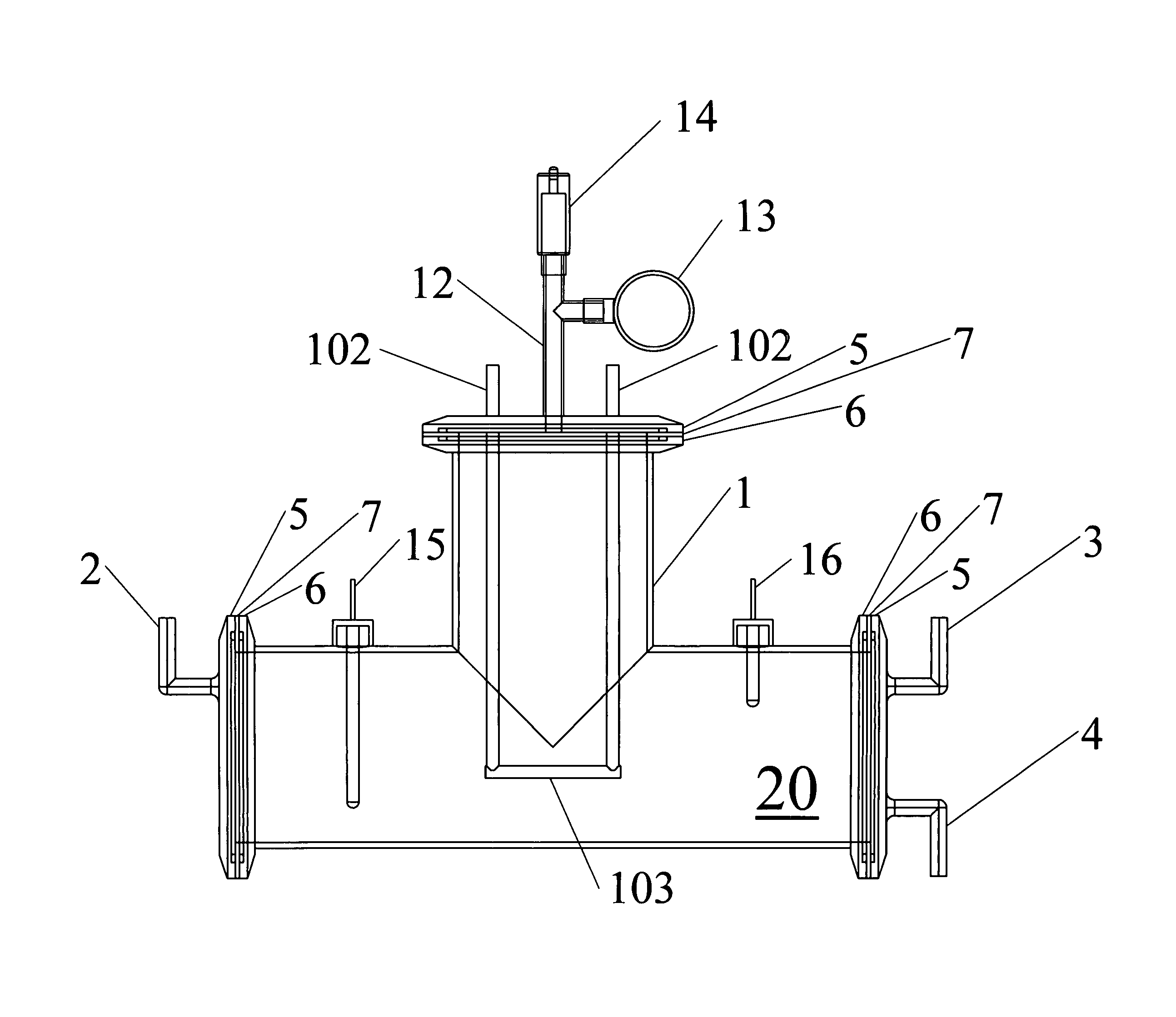
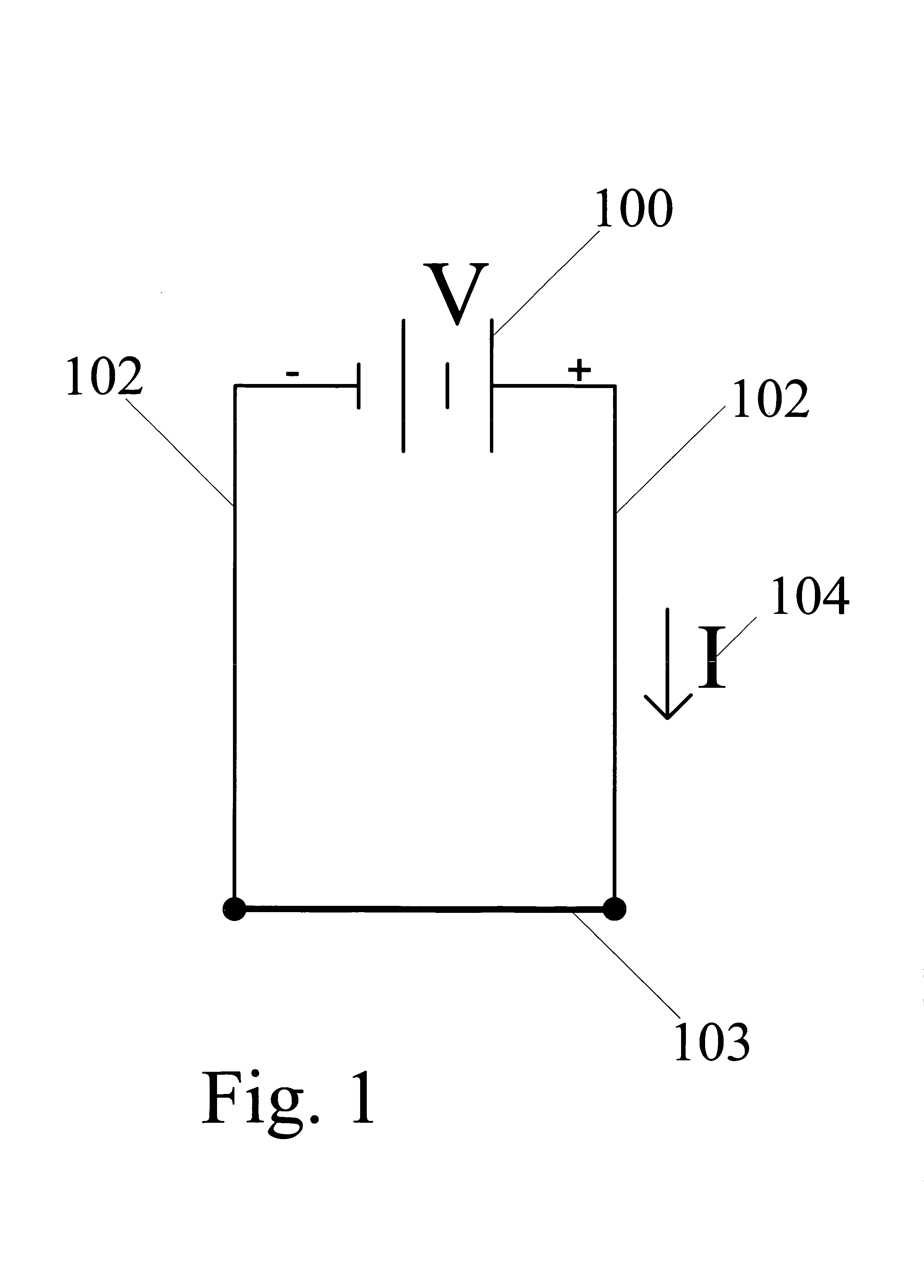
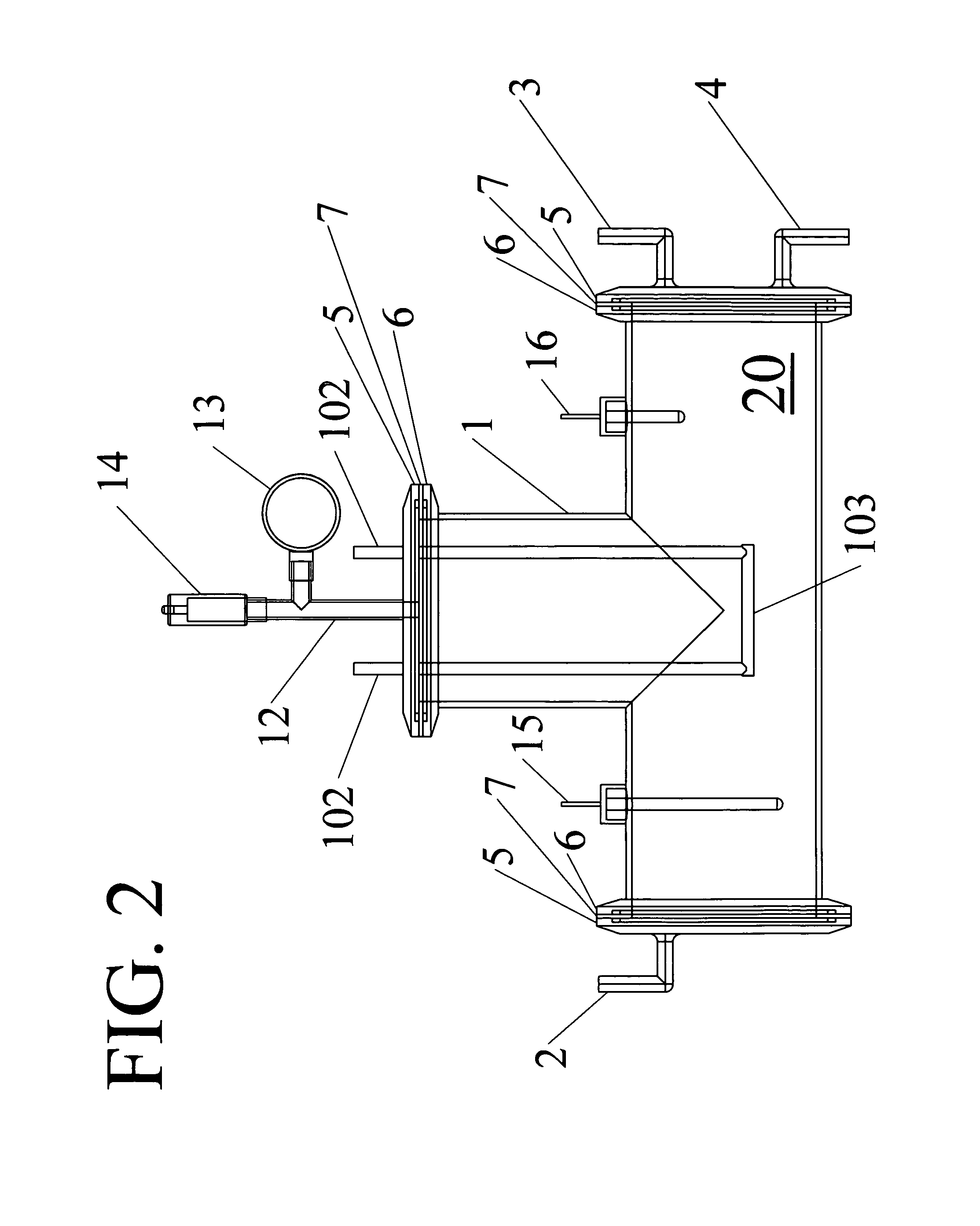
[0006]The thermoelectric reformer is designed to reform organic and inorganic compounds in a liquid, gaseous or vaporized feed stream. Liquid fuel need not be atomized and vaporized through an injector or atomizer before entering to the reactor. It can be directly used in the reactor core. Thermoelectric (ionization or dissociation) reforming occurs in a reactor core containing a number of energy sources. These energy sources generate extremely high temperature heat within the thermoelectric electrode; the heat being emitted as photons or light that carry electromagnetic waves and reacts with fuels in the waves immediate surrounding area. Since heat is generated locally, it will not penetrate far within the reactor core that is surrounded by several ceramic or stainless steel or metal alloy walls. However, additional insulating zones (not shown) surrounding the outer surface of the reactor casing minimize the loss of energy from the reactor core and from the reactor itself. Thus very high energy conversion efficiency is achieved. High-density fibers that are commercially available, (e.g., ceramic fibers composed of alumina, silica, or mullite) can be used as insulation material at the insulation zones. High temperature in the reactor core is obtained from applying electrical voltage and current through a circuit containing thermoelectric materials or bimetals such as Fe—Si, Si—Ge, Sb—Te, Ge—Pb—Te, Pb—Te, Pb—Se, Pb—Se—Te, Bi2Te3, and Sb2Te3.
[0011]In the 21st Century, hydrogen is a clean energy alternative. Hydrogen production from hydrogenous materials (such as hydrocarbons and water) using light-carrying heat-propagating electromagnetic waves is the most effective and fastest way of producing hydrogen. Instant reactions translate to fast start and precision control in commercial applications. Therefore, hydrogen-on-demand technology has the potential to become a mainstream energy technology. Most of the expense and challenge of hydrogen storage technology, especially for the energy and transportation sectors, can be eliminated. This means that a small-scale on-site reformer for stationary distributed power or a compact on-board hydrogen-on-demand reactor for fuel cell vehicles can eliminate the significant capital investments in a dedicated hydrogen storage system such as hydrogen storage tank and hydrogen delivery infrastructure such as H2-refueling stations.
[0012]A primary object of the instant invention is to directly use both high electrical and thermal conductivities of the thermoelectric materials to transmit the electrical energy into light for hydrogen-rich synthetic gas production Among other objects of this invention are solving hydrogen production and delivery issues, providing competitive-priced and affordable, and make the hydrogen economy feasible to consumers, and make a hydrogen-based economy feasible if not practicable.

Problems solved by technology

However, without widespread use of fuel cell vehicles, massive investments in a hydrogen-refueling infrastructure, such as hydrogen refueling stations are not likely to occur.

Method used


Image

  • Thermoelectric reformer unit for hydrogen production
  • Thermoelectric reformer unit for hydrogen production
  • Thermoelectric reformer unit for hydrogen production

Examples


Embodiment Construction

[0019]Traditionally thermoelectric materials are applied to electrical power generators and refrigerative coolers. Both applications require hot and cold junctions with different P-N types of thermoelectric materials. Traditionally based on conversion of thermal (heat) energy to electricity (Seebeck Effect) or of electricity to heat energy (Peltier Effect), for a material to have good thermoelectric properties, it must be a good electrical conductor (i.e., with an electric conductivity greater than 1000 S / cm) and a poor thermal conductor (i.e., with a thermal conductivity less than 2 W / m-K). Because some materials (e.g. carbon such as carbon C60, diamond and graphite; carbon compounds or diamond-like materials such as silicon carbide (SiC) and carbon nitride C3N4) are good at conducting both electricity and heat, some scientists had ruled them out as a possible good thermoelectric material.

[0020]However, we could use special characteristics of such high conductivity material and con...


PUM


Abstract

A thermoelectric reformer unit-for dissociating fossil-based hydrocarbons, renewable hydrocarbons or hydrogen-containing inorganic compounds to produce hydrogen in a reactor using thermoelectric technology with thermoelectric materials to achieve very high conversion efficiencies. Thermoelectric reforming occurs in a reactor core containing a number of energy sources. These energy sources generate extremely high temperature heat that reacts with the fuels in its local surrounding areas. Since the heat is locally generated, it will not penetrate far within the reactor core that is surrounded by walls that act as a casing for the reformer. Synthetic gas produced in the reformer can be fed into internal combustion engines certain, types of fuel cells, or other energy conversion equipment without or with only limited levels of purification. Ancillary components are needed to produce high-purity hydrogen fuel for other types of fuel cells.

Description

BACKGROUND OF THE INVENTION[0001]This invention pertains to the reforming of liquid, gaseous or vaporized hydrocarbons, inorganic compounds, or mixtures thereof, to produce hydrogen for direct use or for use in a fuel cell. More particularly, it pertains to a thermoelectric reformer unit for dissociating fossil-based hydrocarbons (e.g., methane, methanol, ethanol, gasoline, diesel oil, propane), renewable hydrocarbons (e.g., vegetable oils, or biomass oils), or inorganic compounds (e.g., water, ammonia, and hydrogen sulfide) to produce hydrogen in a thermoelectric reactor using thermoelectric technology with thermoelectric materials, including—bimetals to achieve very high conversion efficiencies.[0002]Hydrogen has long been recognized as an ideal fuel for power generation systems with virtually no emissions of air pollutants and greenhouse gases. It can be used in fuel cells or hydrogen-fueled internal combustion engines to power vehicles or to provide electricity and thermal energ...

Claims


Application Information

Patent Timeline
Patent Type & Authority Patents(United States)
IPC IPC(8): B01J19/08B01J8/00B01J10/00B01J7/00B01J19/12
CPCB01J19/2415C01B3/042C01B3/047C01B3/22C01B3/24B01J19/087B01J2219/00063B01J2219/00135B01J2219/00144B01J2219/0815B01J2219/0843B01J2219/0869B01J2219/0871B01J2219/0875B01J2219/0877B01J2219/0884B01J2219/0894C01B2203/0272C01B2203/085C01B2203/1223C01B2203/1229C01B2203/1241Y02E60/364Y02E60/36
Inventor WANG, CHI S.
Owner WANG CHI S
Learn More