
Lead frame for semiconductor device and method of manufacturing of the same

a technology for semiconductor devices and lead frames, which is applied in semiconductor devices, semiconductor/solid-state device details, coatings, etc., can solve the problems of reducing the time required for plating, and achieve the effects of simplifying the structure, strong adhesive properties, and excellent adhesive properties

Active Publication Date: 2012-02-07
PANASONIC HLDG CORP
View PDF9 Cites 0 Cited by
  • Summary
  • Abstract
  • Description
  • Claims
  • Application Information

AI Technical Summary

Benefits of technology

[0024]In the lead frame for a semiconductor device according to the present invention, a predetermined organic film having metal-binding properties is formed between (i) a lower plating layer formed on a conductive base and (ii) an uppermost plating layer. As a result, the lower plating layer and the uppermost plating layer form a metal bond through the organic film, thus guaranteeing strong adhesive properties in the lower plating layer and the uppermost plating layer. Excellent adhesive properties between plating layers are thus achieved without forming an intermediate plating layer as in a conventional structure, thereby simplifying the structure.
[0025]Furthermore, since the lower plating layer is coated by the organic film, the organic film prevents diffusion of metal from the lower plating layer. The organic film also resolves the problems of oxygen in the atmosphere penetrating to the lower plating layer, leading to deterioration in wire bonding properties and solderability, and to an increase in contact resistance.
[0026]By appropriately setting the degree of density of the organic film and the structure of the organic molecules, the organic film not only blocks oxygen in the atmosphere, but is also highly effective at blocking corrosive gasses, humidity, moisture, etc. Therefore, providing an organic film with predetermined properties controls corrosion and oxidation of the conductive base and the lower plating layer and prevents formation of an oxide film on the plating boundary surface. This improves adhesive properties between plating layers and prevents the layers from peeling apart. Therefore, even if holes form in the uppermost plating layer, problems such as corrosion or oxidation of the conductive base and the lower plating layer are prevented by providing an organic film.
[0027]By using such an organic film that prevents corrosion and oxidation of the lower plating layer as well as diffusion of the metal in the base, the uppermost plating layer can be formed thinner than in a conventional structure, which reduces the cost of materials. Furthermore, forming a thinner plating layer reduces the time required for plating, which not only increases manufacturing efficiency, but also contributes to cost reduction by reducing manufacturing lead time.
[0028]The lead frame for a semiconductor device according to the present invention does not depend on the facilities and equipment to form an intermediate plating layer as in conventional technology, thus achieving a major reduction in manufacturing cost. The present invention thus provides a lead frame for a semiconductor device that is inexpensive, highly efficient to manufacture, and that has excellent electrical connection properties.
[0029]From the perspectives of functionality, structure, etc., the lead frame according to the present invention therefore has completely different characteristics than a conventional lead frame in which general plating, surface treatment, etc. have been applied to conductive base material.

Problems solved by technology

Furthermore, forming a thinner plating layer reduces the time required for plating.

Method used


Image

  • Lead frame for semiconductor device and method of manufacturing of the same
  • Lead frame for semiconductor device and method of manufacturing of the same
  • Lead frame for semiconductor device and method of manufacturing of the same

Examples


embodiment 1

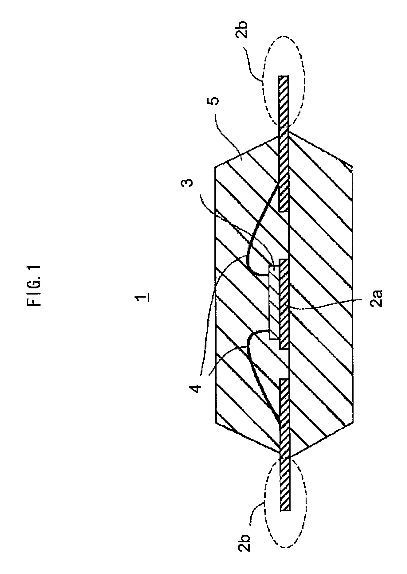
[0038]FIG. 1 is a cross-section diagram showing a structure of a semiconductor device 1 of the present invention.

[0039]The semiconductor device 1 includes a lead frame (2a, 2b) to which predetermined pattering has been applied. A semiconductor element 3 is mounted on an inner lead 2a, and the semiconductor element 3 is connected to outer leads 2b by bonding wires 4. The inner lead 2a, semiconductor element 3, bonding wires 4, and portions of the outer leads 2b are packaged by sealing resin 5.

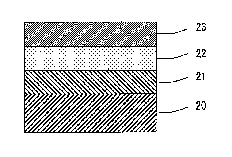
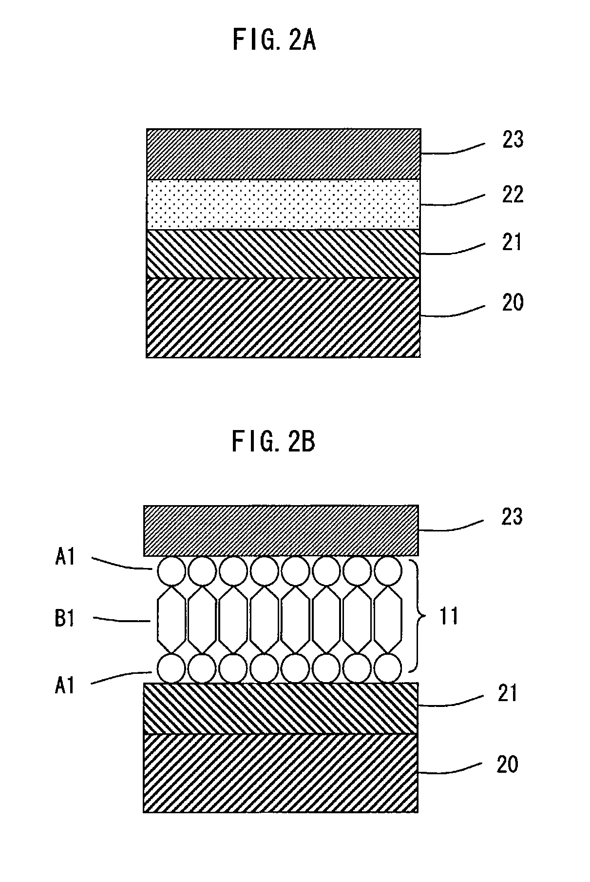
[0040]FIG. 2A is a partial cross-section diagram of the lead frame (2a, 2b) in the semiconductor device 1. The lead frame (2a, 2b) has a laminated structure that includes a conductive base 20, a lower plating layer 21 formed thereon, an uppermost plating layer 23, and an organic film 22 between the lower plating layer 21 and the uppermost plating layer 23. The organic film 22 has metal-binding properties.

[0041]The conductive base 20 is the base of the lead frame (2a, 2b) and is formed from a me...

embodiment 2

[0080]Forming the organic film 22 on the lower plating layer according to the method of manufacturing of Embodiment 2 prevents corrosion and oxidation of the lower plating layer and also prevents diffusion of the metal in the base material. This allows the uppermost plating layer 23 to be formed relatively thin, which reduces the cost of materials. Furthermore, forming a thinner plating layer reduces the time required for plating. Reducing the manufacturing lead time in this way also contributes to cost reduction.

[0081]The method of manufacturing according to the present invention reduces the enormous manufacturing cost that is necessary for facilities and equipment to form an intermediate plating layer, thus achieving a lead frame for a semiconductor device that is low cost, highly efficient to manufacture, and that has excellent electrical connection properties.

[0082]In the above embodiments, the organic film is a monomolecular film whose functional organic molecules self assemble...


PUM


Abstract

Provided are a semiconductor device lead frame and a method of manufacturing of the same that improve adhesive properties between plating layers when a plurality of plating layers are laminated, that control deterioration in wire bonding properties during the manufacturing process of a semiconductor device and worsening of solderability during packaging, and that effectively reduce manufacturing cost. Specifically, the lead frame (2a, 2b) has a laminated structure that includes a lower plating layer (22) formed on a conductive base material (21) and an uppermost plating layer (23), with an organic film (22) that has metal-binding properties formed between the lower plating layer (21) and the uppermost plating layer (23). The organic film (22) is formed as a monomolecular film in which functional organic molecules (11) self assemble. Each of the organic molecules (11) has functional groups (A1, A1) with metal-binding properties on both ends of a main chain (B1).

Description

TECHNICAL FIELD[0001]The present invention relates to lead frames for semiconductor devices, the lead frames having a plurality of plating layers laminated thereon, and in particular to technology for improving adhesive properties between plating layers.BACKGROUND ART[0002]A lead frame formed by a metal body is used as a component for electrical connection in semiconductor elements such as LEDs, LSIs, etc. The semiconductor element is electrically connected to the lead frame by wire bonding. Along with the lead frame, the semiconductor element is sealed with resin during production and is then connected to a substrate or the like in a semiconductor device using, for example, solder.[0003]Excellent wire bonding properties and solderability are required in the manufacturing process of the semiconductor device. To guarantee these properties, a plating layer of a precious metal is sometimes provided in the electrical connection component such as the lead frame. Caution is required, howe...

Claims


Application Information

Patent Timeline
Patent Type & Authority Patents(United States)
IPC IPC(8): H01L23/495
CPCH01L23/49586H01L24/48H01L2224/48091H01L2224/48247H01L2924/01046H01L2924/01078H01L2924/01079H01L2924/00014H01L2924/12044H01L2924/181H01L2924/00H01L2924/00012H01L2224/45099H01L2224/45015H01L2924/207
Inventor IMANISHI, YASUKOFUKUNAGA, TAKAHIRO
Owner PANASONIC HLDG CORP
Learn More