
On-axis illumination for iris imaging

a technology of iris imaging and iris, which is applied in the field of human iris illumination for iris imaging, can solve the problems of limiting the amount of illumination that can be used, limiting the safety of eyes, and dominated by photon noise in image snr, etc., and achieves the effects of extending usable exposure time, high quality, and high quality

Active Publication Date: 2012-01-10
TASCENT INC
View PDF54 Cites 71 Cited by
  • Summary
  • Abstract
  • Description
  • Claims
  • Application Information

AI Technical Summary

Benefits of technology

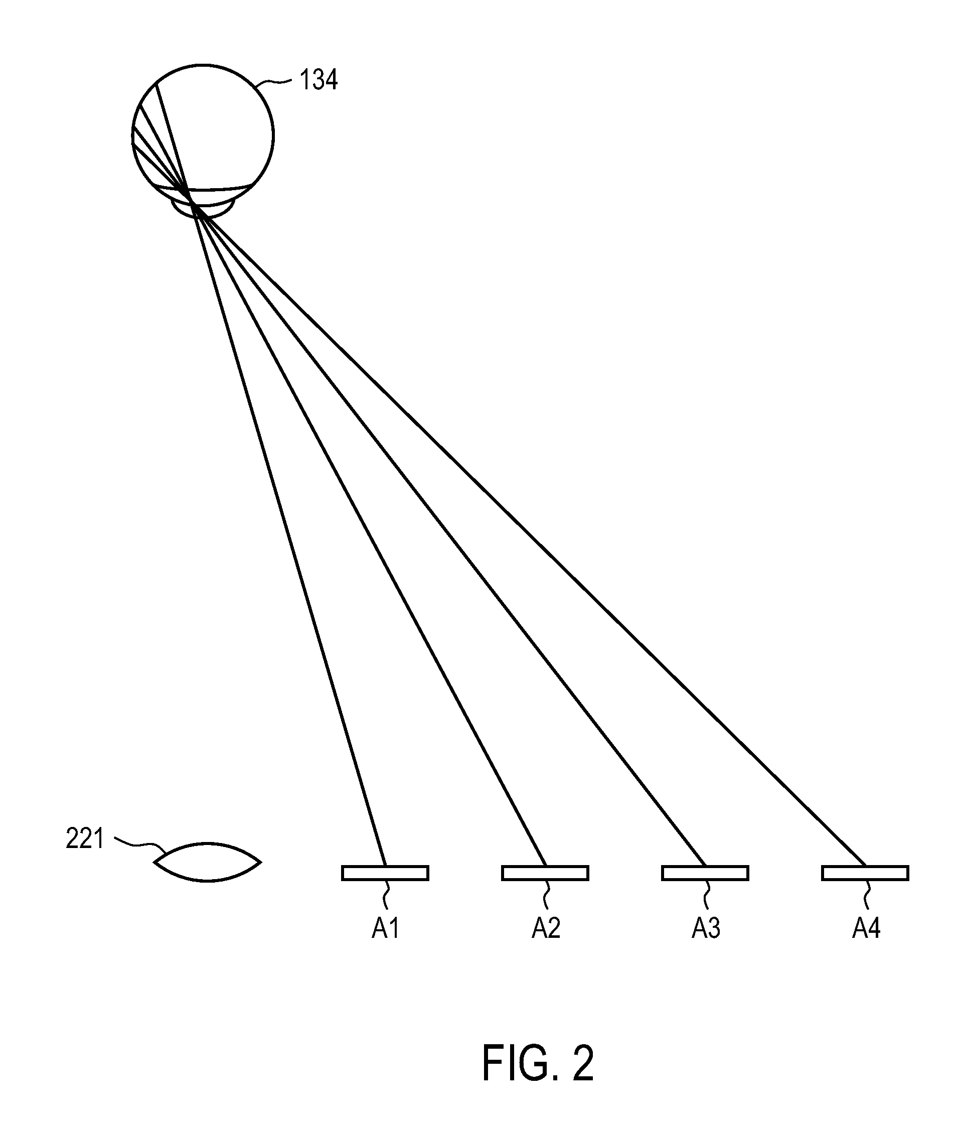
[0009]The present invention provides a rapid, high quality iris imaging system. Light illuminates the subjects' eyes. Reflection from the eyes (e.g., retro-reflection from the retina or glint reflection from the cornea) is used to steer (and preferably also focus) a high resolution camera to the eyes in order to capture images of the irises. The camera captures images of irises with sufficient resolution for biometric identification. Real-time steering and focus correction may extend the usable exposure time, thus allowing good images under lower illumination levels than otherwise possible.
[0010]In one embodiment, on-axis illumination is used to illuminate the subjects' eyes. A single steering mechanism steers both the camera and the illumination, without parallax issues. In one implementation, the illumination beam is combined with the imaging beam along the camera's optical axis on the subject side of the iris camera objective lens. In another implementation, the illumination beam is combined with the imaging beam along the camera's optical axis before the fine steering and focus (and possibly higher order aberrations) correction mechanism. In a pre-correction configuration, the iris illumination spot can be reduced in size to be only slightly larger than the iris. In both the pre and post-correction configuration, the eye safety limits will be most critical at the subject, which allows for maximization of the illumination flux.

Problems solved by technology

One of the most challenging aspects of iris imaging for biometric purposes is arranging to obtain adequate light level at the iris to obtain high signal to noise ratio (SNR) images.
At the same time, eye safety limits constrain the amount of illumination that can be used.
With modern CCD or CMOS imagers, the noise of the devices is already low enough that the image SNR is dominated by photon (quantum shot) noise at the intensity levels of interest.
This puts significant constraints on the design of illumination systems, because in practice they are required to be eye safe even if someone looks directly into the illumination aperture.
At shorter wavelengths, closer to the conventional visible wavelength band, the eye safety limitations become more stringent.
Furthermore, at visible wavelengths, light of sufficient intensity may become too bright to look at, thus triggering the aversion response.
However, at longer wavelengths, the transparency of the iris material increases, which leads to significant changes in the image morphology.
Thus, use of wavelengths significantly longer than 850 nm may result in images that are incompatible with expositing iris coding algorithms and databases.
Incompatibility with expositing algorithms does not necessarily obviate the usefulness of longer wavelengths, but will nevertheless impact marketability of a longer wavelength solution.
The responsivity of inexpensive silicon based detectors also falls very rapidly as wavelengths increase past 850 nm, making detection of long wavelength light increasingly expensive.
Increasing the illumination time increases the possibility of motion blur.
There are cost constraints to building very fast lenses, but more significant is the effect on depth of field.
If the camera is statically focused, a smaller depth of field also limits the probability that the subject will be within the focus range.
Increasing the numerical aperture without increasing the detector pixel pitch, can lead to aliasing errors, where high frequency image structure appears incorrectly as low frequency features.

Method used


Image

  • On-axis illumination for iris imaging
  • On-axis illumination for iris imaging
  • On-axis illumination for iris imaging

Examples


Embodiment Construction

1. Portal Illumination

[0020]FIG. 1 is an illustration of an iris imaging system using off-axis illumination devices 150 mounted on a portal 60. The iris imaging system includes an imaging subsystem 200. The system is designed to capture iris images of many eyes 134, typically without the active cooperation of the subjects. In one application, the subjects are passing through a portal 60 (such as a doorway, hallway, or metal detector); the iris imaging system captures iris images as the subjects pass through. Examples include corridors, turnstiles, toll booths, elevator doors, escalators and parking garage entrances. Other examples include checkout lines or other queues, crosswalks, sidewalks and roadways.

[0021]This situation typically is “uncooperative,” meaning that the subjects are not actively cooperating in the iris imaging. For example, they are not placing their heads into a device to allow capture of iris images. Rather, they are simply walking through the portal 60 and the i...


PUM


Abstract

The present invention provides a rapid, high quality iris imaging system. In one embodiment, on-axis illumination is used. A single steering mechanism steers both the camera and the illumination, without parallax issues. The illumination beam can be combined along the camera's optical axis before or after the fine steering and focus correction mechanism. In a pre-correction configuration, the iris illumination spot can be reduced in size to be only slightly larger than the iris. In both the pre and post-correction configuration, the eye safety limits will be most critical at the subject, which allows for maximization of the illumination flux.

Description

CROSS-REFERENCE TO RELATED APPLICATION(S)[0001]This application claims priority from U.S. Provisional Patent Application Ser. No. 60 / 886,888, filed Jan. 26, 2007, entitled “On-Axis Illumination for Iris Imaging.” This application is related to U.S. patent application Ser. No. 11 / 765,401, filed Jun. 19, 2007, entitled “Iris Imaging Using Reflection From The Eye,” and U.S. patent application Ser. No. 11 / 297,578, filed on Dec. 7, 2005, entitled “Iris Imaging Using Reflection From The Eye.” The subject matter of all of the foregoing is incorporated herein by reference in their entirety.BACKGROUND OF THE INVENTION[0002]1. Field of the Invention[0003]This invention relates to illumination of the human iris for iris imaging, as may be used for biometric identification.[0004]2. Description of the Related Art[0005]One of the most challenging aspects of iris imaging for biometric purposes is arranging to obtain adequate light level at the iris to obtain high signal to noise ratio (SNR) images...

Claims


Application Information

Patent Timeline
IPC IPC(8): A61B3/14A61B3/10
CPCA61B3/1015A61B3/152A61B3/0008A61B3/1216G06V40/19
Inventor NORTHCOTT, MALCOLM J.GRAVES, J. ELON
Owner TASCENT INC
Learn More