Manufacturing method for worm wheel, and worm gear reducer
a technology manufacturing method, which is applied in the direction of gear teeth, gear teeth, gear manufacturing apparatus, etc., can solve the problems of increased contact pressure, increased manufacturing cost difficulty in ensuring so as to prevent the meshing portion and ensure the durability of worm gear reducer. , the effect of preventing the meshing portion
- Summary
- Abstract
- Description
- Claims
- Application Information
AI Technical Summary
Benefits of technology
Problems solved by technology
Method used
Image
Examples
embodiment 1
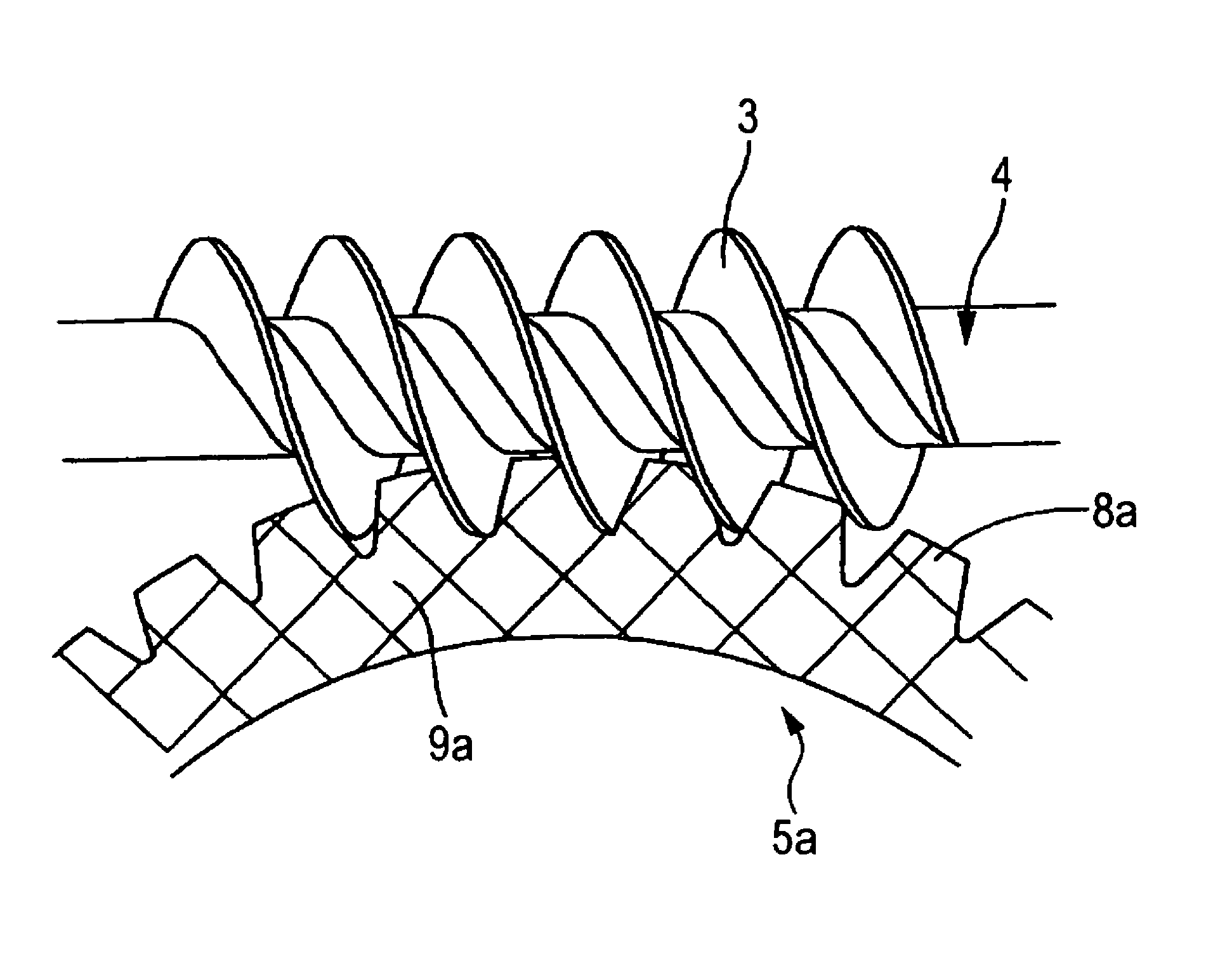
[0082]FIGS. 1 to 6 are views showing Embodiment 1 of the present invention which corresponds to the first and fourth through eighth aspects of the present invention. In this connection, the characteristics of this embodiment are the manufacturing method for a worm wheel 5a and the structure of a worm gear reducer including the worm wheel 5a. The structure and operation of the other portions are the same as those of the conventional structure shown in FIG. 17. Therefore, the duplicated drawings and explanations are omitted or simplified here, and the characteristic portions of this embodiment will be mainly explained as follows.
[0083]In this embodiment, as the tool used for machining the tooth portion 8a of the worm wheel 5a, the machining worm 13 shown in FIG. 1B is used. This machining worm 13 is composed in such a manner that a large number of abrasive grains 14, 14 (shown only in FIG. 2) are electro-deposited on the surface thereof, of which shape and size are the same as those o...
embodiment 2
[0092]FIGS. 7 to 11 are views showing Embodiment 2 of the present invention which corresponds to the first and fourth through eighth aspects of the present invention. In this embodiment, concerning the tool used for machining the tooth portion 8b of the worm wheel 5b, the machining worm 13a shown in FIG. 7B is used. This machining worm 13a is composed in such a manner that a large number of abrasive grains 14, 14 (shown in FIG. 2) are electro-deposited on the surface of the worm, the shape and size of which are the same as those of the operational worm 3 meshed with the tooth portion 8b of the worm wheel at the time of use as shown in FIGS. 7A and 11. In this connection, the fine hatched portions (which can be seen as if they were painted out black) shown in FIG. 7B, is a portion in which a large number of abrasive grains 14, 14 are electro-deposited. Due to the foregoing, the portion, on which a large number of abrasive grains are electro-deposited in the machining worm 13a, is mad...
embodiment 3
[0097]FIGS. 12 and 13 are views showing Embodiment 3 of the present invention which corresponds to the first and fourth through eighth aspects of the present invention. In the case of Embodiment 1 described before, an object to be manufactured is the worm wheel 5a which is meshed with the cylindrical operational worm 3. On the other hand, in this embodiment, as shown in FIG. 13, an object to be manufactured is the worm wheel 5c which is meshed with the middle-recessed drum worm 3a. In this embodiment, in the same manner as that of Embodiment 1 described before, the machining worm 13b shown in FIG. 12B is composed in such a manner that a large number of abrasive grains 14, 14 (shown in FIG. 2) are electro-deposited on a surface of the middle-recessed drum worm, the shape and size of which are the same as those of the operational worm 3a at the time of use shown in FIGS. 12A and 13. In this connection, the fine hatched portion (which can be seen as if they were painted out black) show...
PUM
| Property | Measurement | Unit |
|---|---|---|
| surface roughness | aaaaa | aaaaa |
| size | aaaaa | aaaaa |
| size | aaaaa | aaaaa |
Abstract
Description
Claims
Application Information
 - R&D
- Intellectual Property
- Life Sciences
- Materials
- Tech Scout
- Unparalleled Data Quality
- Higher Quality Content
- 60% Fewer Hallucinations
Browse by: Latest US Patents, China's latest patents, Technical Efficacy Thesaurus, Application Domain, Technology Topic, Popular Technical Reports.
© 2025 PatSnap. All rights reserved.Legal|Privacy policy|Modern Slavery Act Transparency Statement|Sitemap|About US| Contact US: help@patsnap.com


