
Articles having improved resistance to thermal cracking

a technology of cemented carbide and thermal cracking, which is applied in the field of articles having improved resistance to thermal cracking, can solve the problems of thermal cracking in articles comprising cemented carbides, cracks may be initiated in such articles, and achieve the effect of improving the resistance to certain modes of thermal failur

Active Publication Date: 2011-08-30
KENNAMETAL INC
View PDF408 Cites 44 Cited by
  • Summary
  • Abstract
  • Description
  • Claims
  • Application Information

AI Technical Summary

Benefits of technology

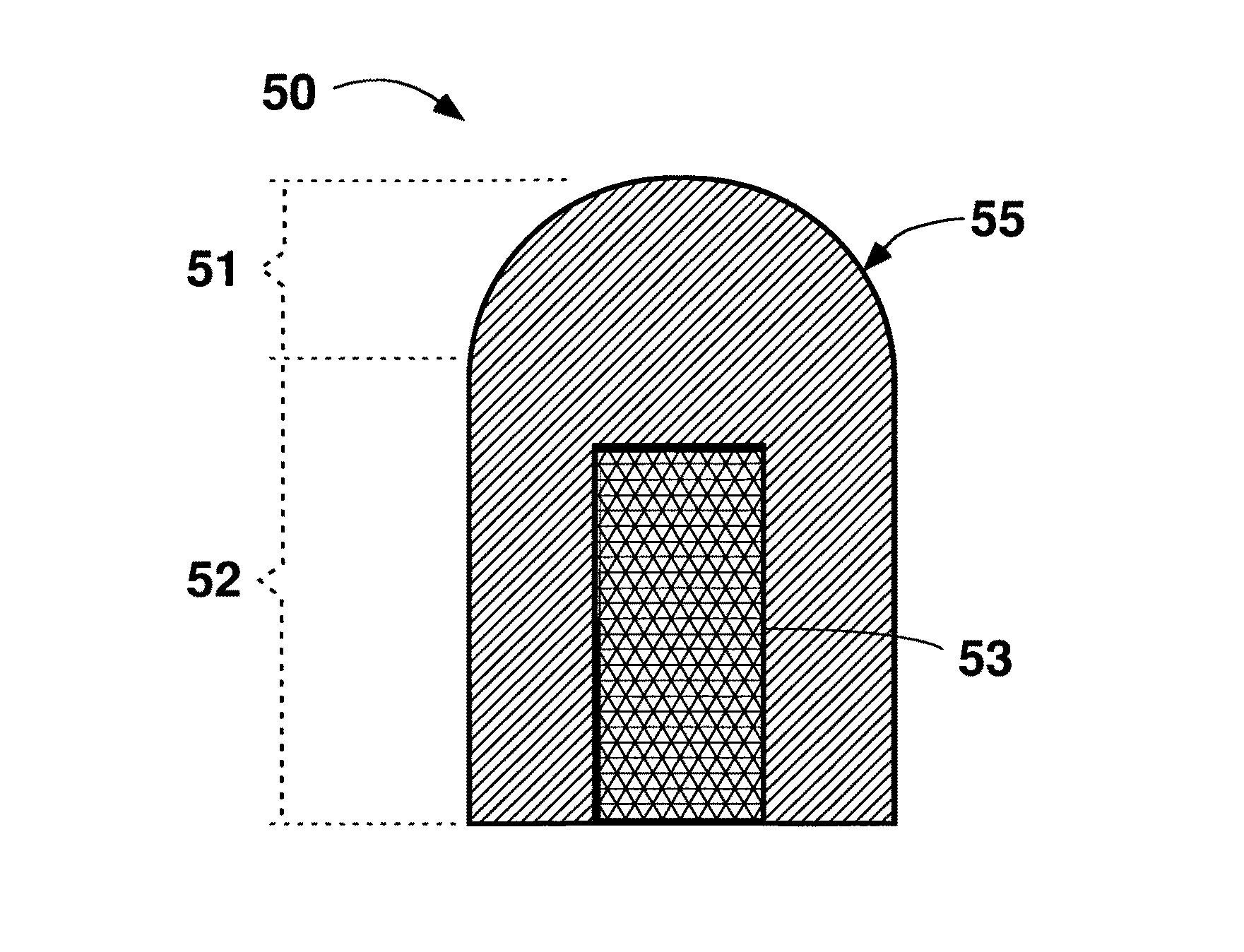
The invention relates to improvements to articles made of cemented carbide, which includes hard particles of carbides of at least one transition metal selected from titanium, chromium, vanadium, zirconium, hafnium, tantalum, molybdenum, niobium, and tungsten. The invention provides articles with a heat sink portion that includes a material with greater thermal conductivity than the cemented carbide, which helps to prevent thermal failure. The heat sink portion can be in thermal communication with the working portion of the article, which is in contact with the body portion. The invention also provides methods for making the improved articles.

Problems solved by technology

Articles comprising cemented carbides tend to fail by thermal cracking.
Cracks in such articles may be initiated if the article is heated above a threshold value, and the cracks may further propagate if the article is subject to thermal cycling.
Thus, there is a trade-off between wear resistance and fracture toughness when selecting a cemented carbide grade for any application.
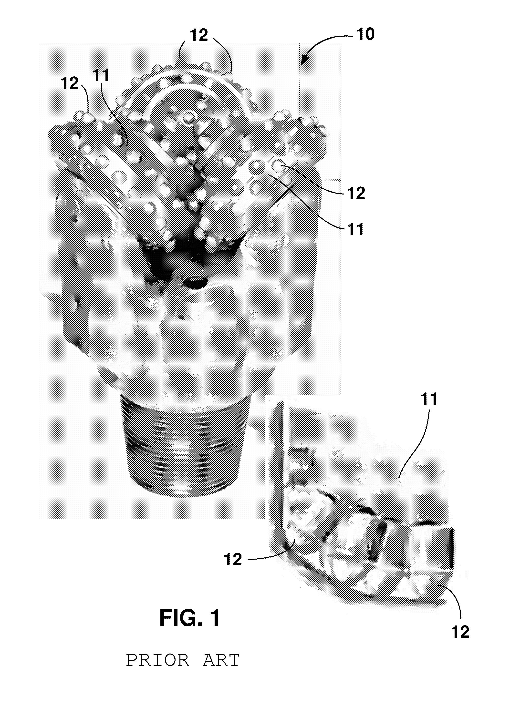
As rubbing action continues, considerable heat may be generated by the increase in friction between the rock and the cutting insert, thereby resulting in heating of portions of the insert.
If the temperature of any portion of the article exceeds a threshold value, cracks will be initiated at the interface of the hard particles and the binder.
Thermal cycling of the article causes propagation of the cracks.

Method used


Image

  • Articles having improved resistance to thermal cracking
  • Articles having improved resistance to thermal cracking
  • Articles having improved resistance to thermal cracking

Examples


Embodiment Construction

[0030]Unless otherwise indicated, all numbers expressing quantities of ingredients, time, temperatures, and so forth used in the present specification and claims are to be understood as being modified in all instances by the term “about.” Accordingly, unless indicated to the contrary, the numerical parameters set forth in the following specification and claims are approximations that may vary depending upon the desired properties sought to be obtained by the present invention. At the very least, and not as an attempt to limit the application of the doctrine of equivalents to the scope of the claims, each numerical parameter should at least be construed in light of the number of reported significant digits and by applying ordinary rounding techniques.

[0031]Notwithstanding that the numerical ranges and parameters setting forth the broad scope of the invention are approximations, the numerical values set forth in the specific examples are reported as precisely as possible. Any numerica...


PUM

PropertyMeasurementUnit
weight percentaaaaaaaaaa
grain sizeaaaaaaaaaa

Abstract

An article includes a working portion including cemented carbide, and a heat sink portion in thermal communication with the working portion. The heat sink portion includes a heat sink material having a thermal conductivity greater than a thermal conductivity of the cemented carbide. Also disclosed are methods of making an article including a working portion comprising cemented carbide, and a heat sink portion in thermal communication with the working portion and including a heat sink material having a thermal conductivity that is greater than a thermal conductivity of the cemented carbide. The heat sink portion conducts heat from the working portion.

Description

CROSS-REFERENCE TO RELATED APPLICATIONS[0001]The present application claims priority under 35 U.S.C. §119(e) to U.S. provisional patent application Ser. No. 60 / 854,348, filed Oct. 25, 2006.FIELD OF TECHNOLOGY[0002]This invention relates to improvements to articles comprising cemented carbides, such as cutting tools, cutting inserts, seal rings, rolling mill rolls, cutting elements for earth boring bits, as well as other articles subject to heat and / or thermal cycling. The invention also relates to methods of producing such articles. More specifically, the certain embodiments of the invention relate to cemented carbide articles with improved thermal cracking resistance.BACKGROUND OF THE INVENTION[0003]Articles comprising cemented carbides are commonly used in applications that involve high stresses and friction, such as cutting tools or cutting inserts for use in turning, milling, and drilling; seal rings for agitators and pumps; and rolls for rolling steel. Articles comprising cemen...

Claims


Application Information

Patent Timeline
Patent Type & Authority Patents(United States)
IPC IPC(8): B32B7/04E21B10/46B32B7/00B22F7/04F16J15/00E21B27/00B22F7/02
CPCB22F7/062B23B27/045B23B27/10B23B27/141C22C29/06E21B10/52E21B10/567Y10T407/23B22F2005/002B22F2998/00B23B2222/04B23B2222/24B23B2222/28B23B2222/76B23B2224/08B23B2226/12B23B2226/31B23B2226/72B23B2250/12B23B2250/125C22C2204/00B22F2005/001Y10T428/24942Y10T428/12028C22C29/005C22C29/067Y10T83/293B21B27/02B22F7/06
Inventor MIRCHANDANI, PRAKASH K.MOSCO, ALFRED J.OLSEN, ERIC W.CALDWELL, STEVEN G.
Owner KENNAMETAL INC
Learn More