
Composite article with coolant channels and tool fabrication method

a technology of coolant channel and composite article, which is applied in the field of forming articles, can solve the problems of inherently limiting the performance and range of applications of rotary tools, drills and other rotary tools having a monolithic construction, and not experiencing uniform wear and/or chipping and cracking of the cutting edge of the tool, and relatively short service life of such drills

Active Publication Date: 2006-12-28
KENNAMETAL INC
View PDF100 Cites 57 Cited by
  • Summary
  • Abstract
  • Description
  • Claims
  • Application Information

AI Technical Summary

Benefits of technology

[0013] The reader will appreciate the foregoing details and advantages of the present invention, as well as others, upon consideration of the following detailed description of embodiments of the invention. The reader also may comprehend such additional details and advantages of the present invention upon using the invention.

Problems solved by technology

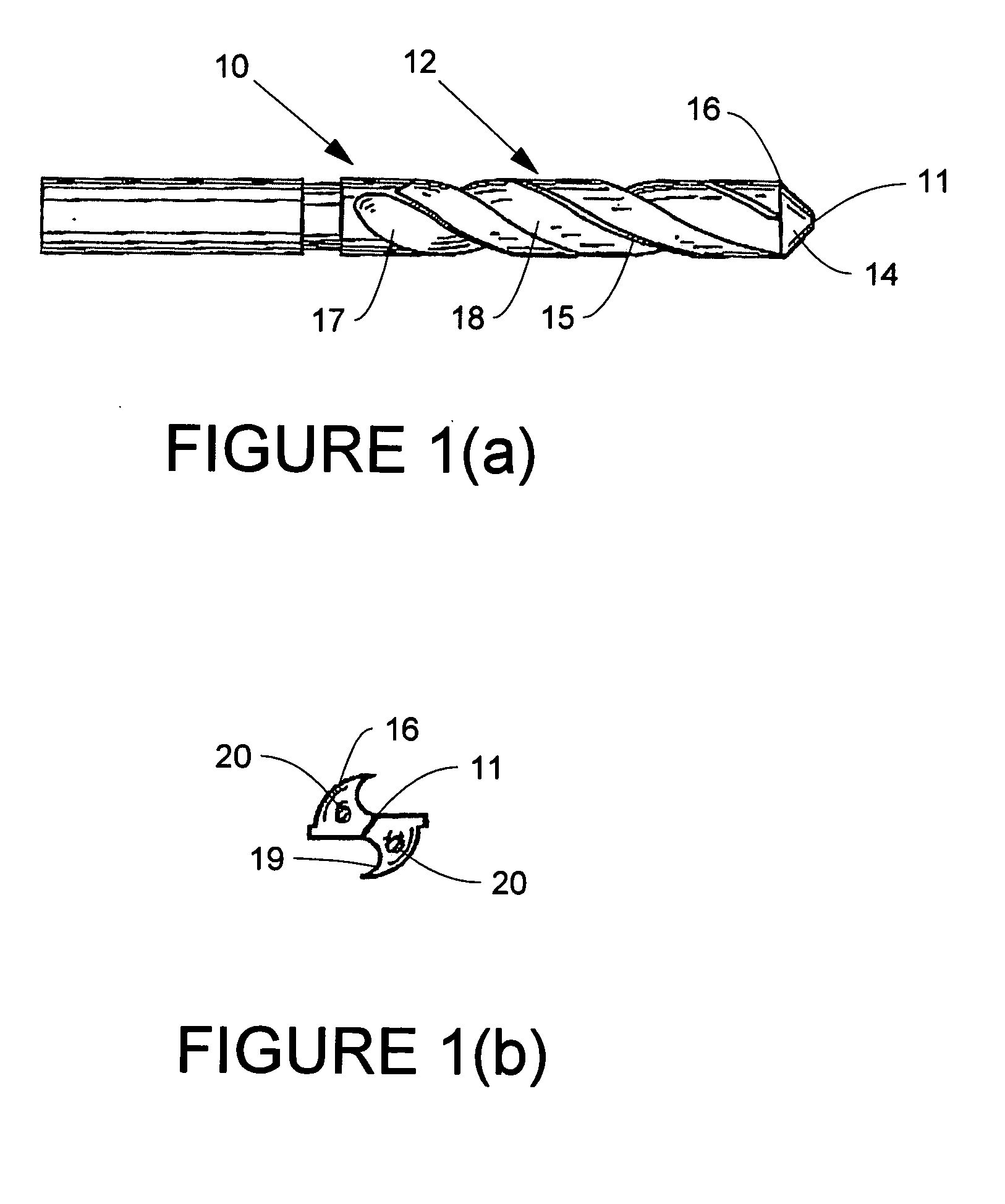
However, the monolithic construction of rotary tools inherently limits their performance and range of applications.
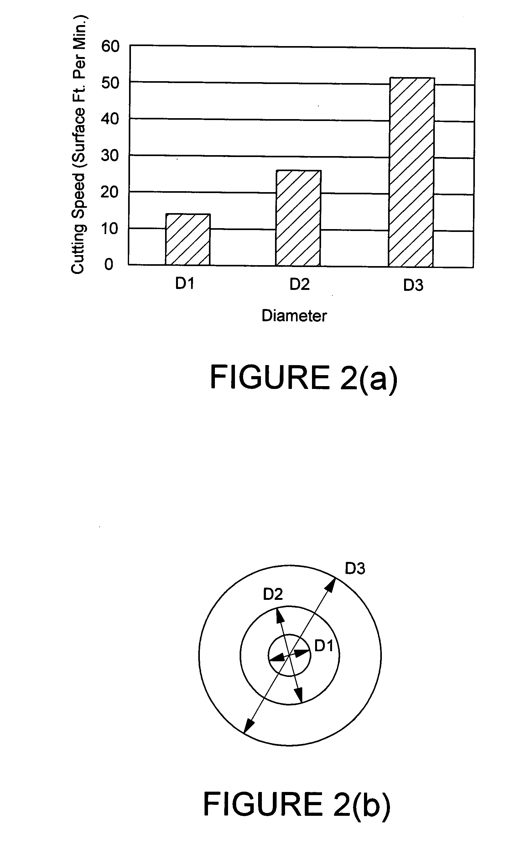
Because of these variations in cutting speed, drills and other rotary tools having a monolithic construction will not experience uniform wear and / or chipping and cracking of the tool's cutting edges at different points ranging from the center to the outside edge of the tool's cutting surface.
Therefore, the chisel edge of conventional drills of monolithic construction used in that application will wear at a much faster rate than the remainder of the cutting edge, resulting in a relatively short service life for such drills.
In both instances, because of the monolithic construction of conventional cemented carbide drills, frequent regrinding of the cutting edge is necessary, thus placing a significant limitation on the service life of the bit.
Frequent regrinding and tool changes also result in excessive downtime for the machine tool that is being used.

Method used


Image

  • Composite article with coolant channels and tool fabrication method
  • Composite article with coolant channels and tool fabrication method
  • Composite article with coolant channels and tool fabrication method

Examples


Embodiment Construction

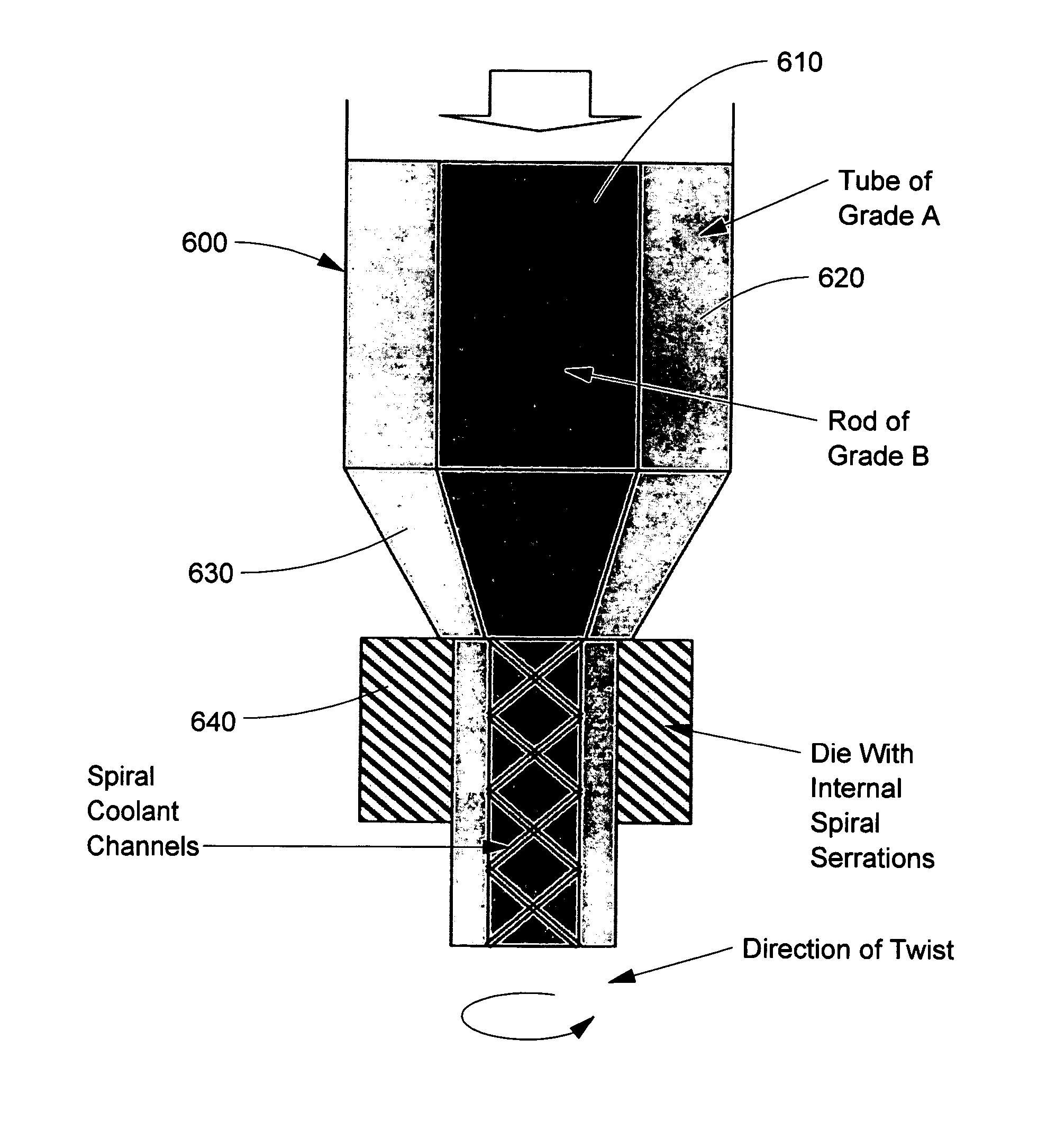
[0026] The present invention provides rotary cutting tools, cutting tool blanks, rods, and other articles having a composite construction and a method of making such articles. The articles may further comprise internal channels, such as coolant channels, if desired. As used herein, a rotary tool is a tool having at least one cutting edge that is driven to rotate. As used herein, “composite” construction refers to an article having regions differing in chemical composition and / or microstructure. These differences result in the regions having properties differing with respect to at least one characteristic. The characteristic may be at least one of, for example, hardness, tensile strength, wear resistance, fracture toughness, modulus of elasticity, corrosion resistance, coefficient of thermal expansion, and coefficient of thermal conductivity. Composite rotary tools that may be constructed as provided in the present invention include drills and end mills, as well as other tools that m...


PUM

PropertyMeasurementUnit
weight percentaaaaaaaaaa

Abstract

Embodiments of the present invention include composite articles comprising at least a first region and a second region and methods of making such articles. The first region may comprise a first composite material, wherein the first region comprises less than 5 wt. % cubic carbides by weight, and the second region may comprise a second composite material, wherein the second composite material differs from the first composite material in at least one characteristic. The composite article may additionally comprise at least one coolant channel. In certain embodiments, the first and second composite material may individually comprise hard particles in a binder, wherein the hard particles independently comprise at least one of a carbide, a nitride, a boride, a silicide, an oxide, and solid solutions thereof and the binder comprises at least one metal selected from cobalt, nickel, iron and alloys thereof. In specific embodiments, the first composite material and the second composite material may individually comprise metal carbides in a binder, such as a cemented carbide.

Description

TECHNICAL FIELD AND INDUSTRIAL APPLICABILITY OF THE INVENTION [0001] The present invention is generally directed to methods of forming articles, such as tool blanks, having a composite construction including regions of differing composition and / or microstucture. The present invention is additionally directed to rotary tools and tool blanks for rotary tools having a composite construction and at least one coolant channel. The method of the present invention finds general application in the production of rotary tools and may be applied in, for example, the production of cemented carbide rotary tools used in material removal operations such as drilling, reaming, countersinking, counterboring, and end milling. DESCRIPTION OF THE INVENTION BACKGROUND [0002] Cemented carbide rotary tools (i.e., tools driven to rotate) are commonly employed in machining operations such as, for example, drilling, reaming, countersinking, counterboring, end milling, and tapping. Such tools are typically of a...

Claims


Application Information

Patent Timeline
Patent Type & Authority Applications(United States)
IPC IPC(8): B21K5/04B29C48/18
CPCB21C23/22Y10T428/131B22F5/10B22F7/06B22F2005/001B22F2005/004B22F2998/10B21C25/02Y10T407/19Y10T408/907Y10T407/1904Y10T428/1317B29C47/06B22F2998/00B22F3/20B22F3/04B22F5/106B29C48/18B23P15/28B22F7/00
Inventor MIRCHANDANI, PRAKASH K.WALLER, MICHAEL E.WEIGOLD, JEFFREY L.SWEARENGIN, BILLY D.
Owner KENNAMETAL INC
Learn More