Conductive catalyst particles and process for production thereof, gas-diffusing catalytic electrode, and electrochemical device

a technology of catalytic electrode and catalyst, which is applied in the direction of catalyst activation/preparation, metal/metal-oxide/metal-hydroxide catalyst, chemical/physical process, etc., can solve the problem of platinum which has been isolated from gas by the ionic conductor and is not functional any longer, and requires steps for reduction and thermal treatment. , to achieve the effect of less amount of catalytic material, good catalytic activity and good crystallinity

Inactive Publication Date: 2011-08-02
SONY CORP
View PDF33 Cites 3 Cited by
  • Summary
  • Abstract
  • Description
  • Claims
  • Application Information

AI Technical Summary

Benefits of technology

[0021]The present inventors have found that preventing the catalytic material from suffering sintering requires that the catalytic material should not experience self-diffusion in its crystal lattice. The present inventions have also found that the internal self-diffusion can be avoided if an insoluble substance (which, even when heated, does not form alloy with a noble metal by solid solution) is compulsorily introduced into the crystal lattice of a noble metal, and the resulting product can be used as the catalytic material which is free of sintering. Their researches also led to the finding that the crystal grains of the catalytic material can be made fine if a solid-insoluble substance is compulsorily introduced into the crystal lattice of a noble metal as the catalytic material. The catalytic material containing such a solid-insoluble substance is inhibited from crystal growth, and hence it exhibits a good catalytic activity. The present invention is based on these findings.
[0032]The electrochemical device according to an embodiment of the present invention, in which at least one of the electrodes is the first or second gas-diffusing electrode, produces the effect of preventing the occurrence of sintering. Therefore, it has good output characteristics and keeps them over a long period of time.

Problems solved by technology

The conventional process mentioned above, however, has the disadvantage of requiring steps for reduction and thermal treatment.
With thermal treatment at an inadequately low temperature, it renders platinum poor in crystallinity, which results in failure of obtaining favorable catalytic characteristics.
Unfortunately, the platinum which has been isolated from gas by the ionic conductor is not functional any longer because it functions only at its specific parts in contact with gas.
This process, however, still needs thermal treatment to improve platinum in crystallinity.
Thermal treatment at temperatures high enough for desired crystallinity deteriorates the ionic conductor which is usually poor in heat resistance.
Moreover, production in this manner requires a large amount of platinum.
Therefore, it has a low catalytic efficiency for its quantity.
Another problem is that the platinum 27 enters pores existing in the surface of the carbon particle (not shown.)
Thus, the platinum 27 partly remains unfunctional and hence is poor in catalytic efficiency for its quantity.
Unfortunately, the ionic conductor 11 is usually poor in heat resistance and becomes deteriorated when heated at a sufficiently high temperature to improve the platinum 27 in crystallinity.
However, the highly pure catalyst adhering to the surface of the conductive powder has the disadvantage of being subject to sintering between the catalytic particles.
However, they decrease in catalytic activity due to sintering as temperature increases with the lapse of time.
Another problem with sintering is that a fuel cell decreases in output if it has a gas-diffusing catalytic electrode based on the conductive catalytic particles containing a highly pure catalyst.
However, a highly pure catalyst tends to increase in the crystal particle diameter.

Method used


Image

  • Conductive catalyst particles and process for production thereof, gas-diffusing catalytic electrode, and electrochemical device
  • Conductive catalyst particles and process for production thereof, gas-diffusing catalytic electrode, and electrochemical device
  • Conductive catalyst particles and process for production thereof, gas-diffusing catalytic electrode, and electrochemical device

Examples


example 1

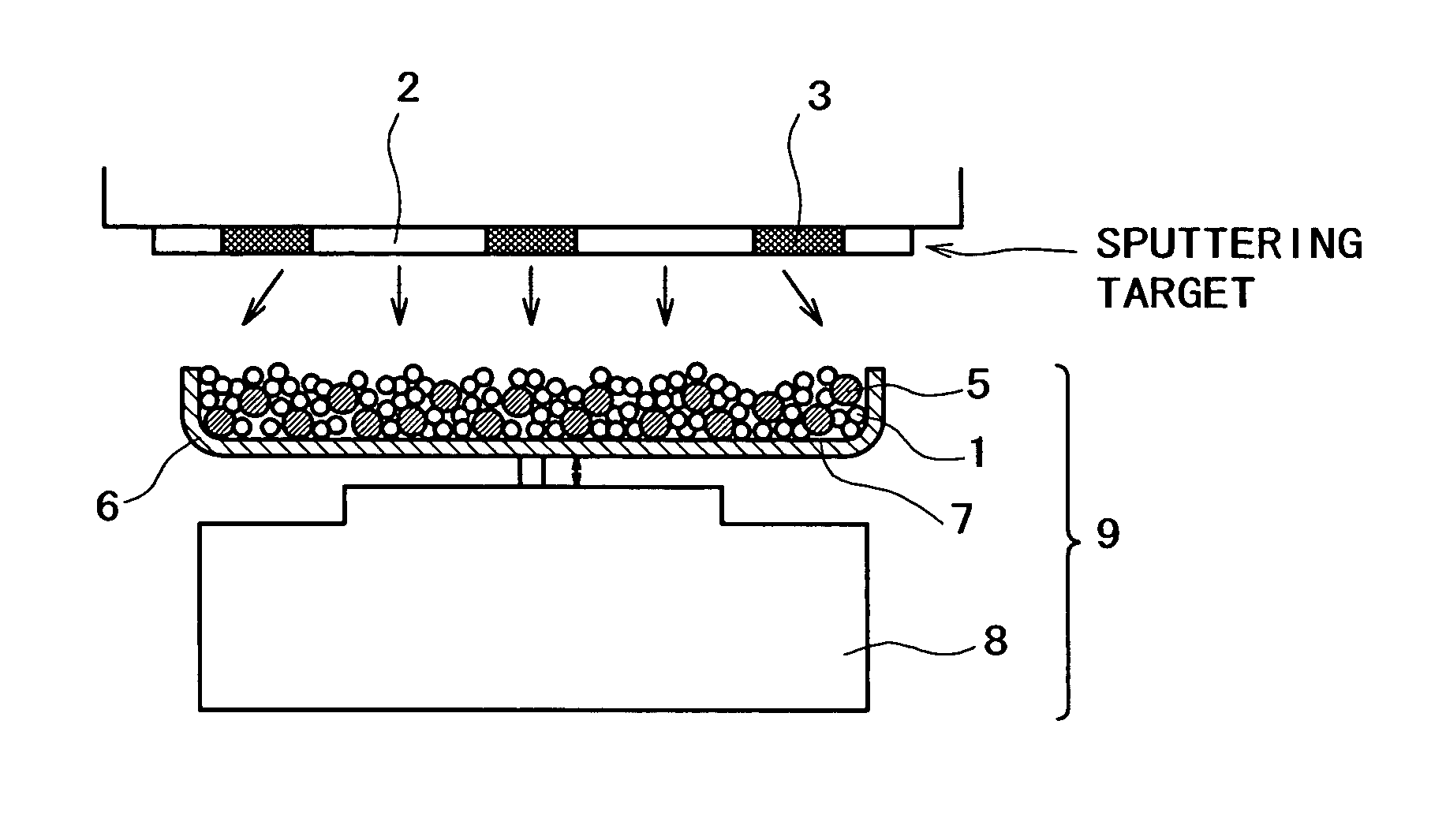
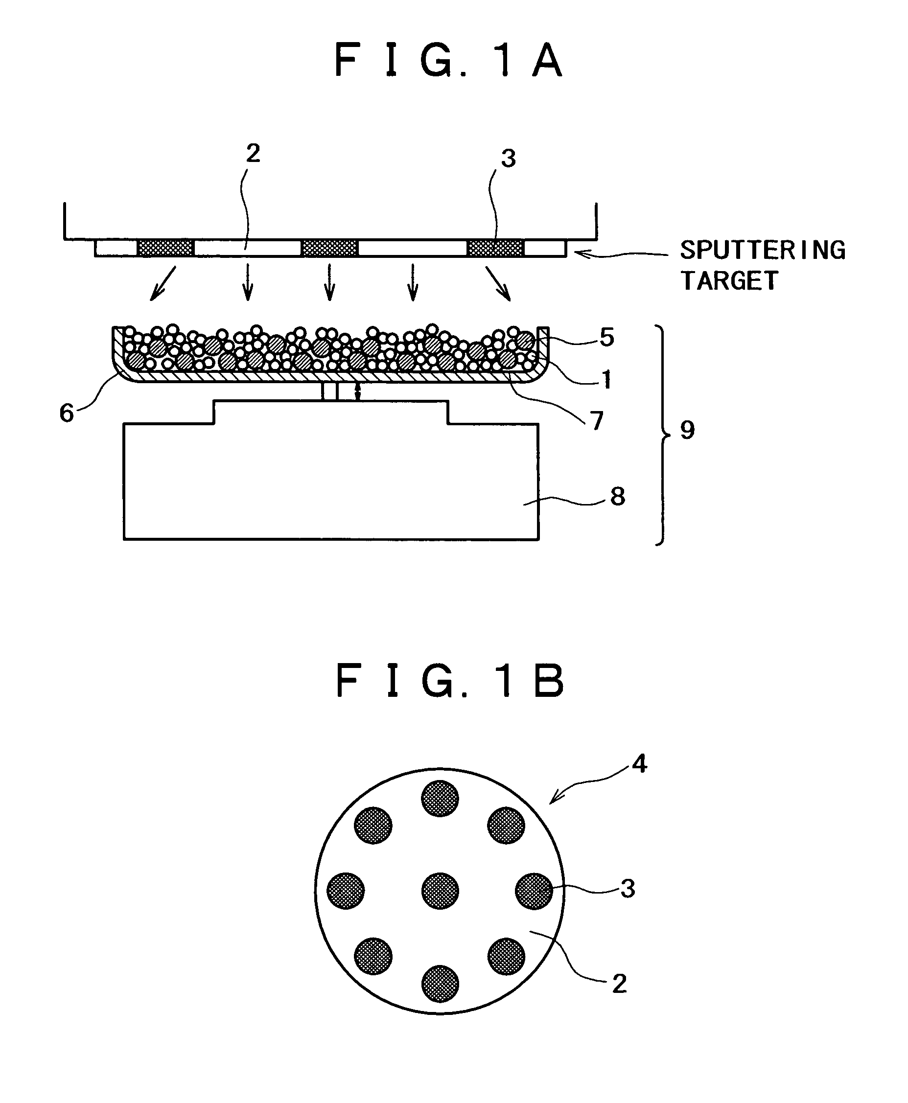
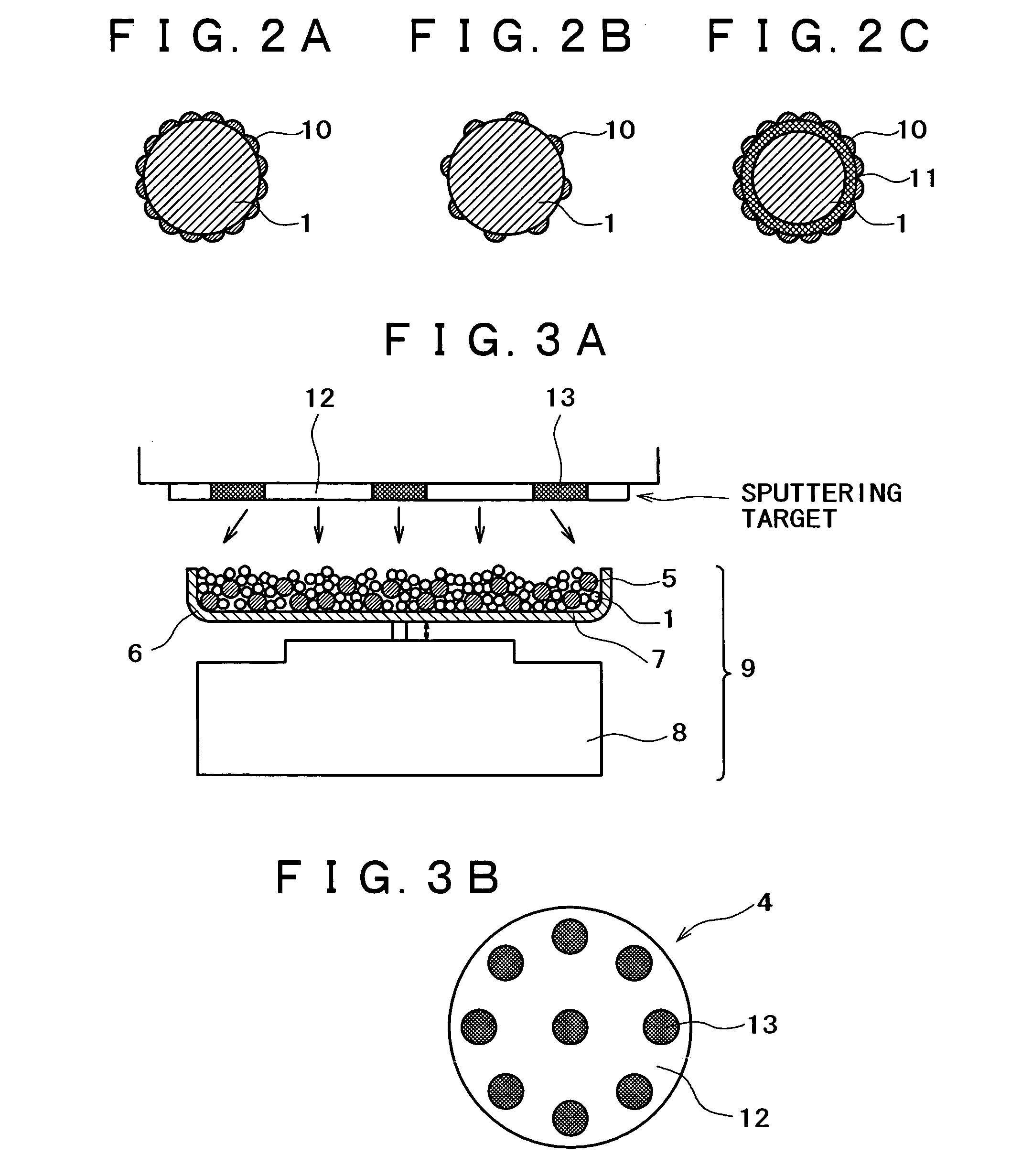
[0150]An apparatus shown in FIG. 1 was assembled from a sputtering target, a vibrator, and a container. The container was charged with a conductive powder and balls. The sputtering target (shown in FIG. 1B) is a platinum disk 100 mm in diameter, which is incorporated with boron (B) in such an amount that the film formed by sputtering contains as much boron as shown in Table 1 given below. The balls are stainless steel balls 3 mm in diameter. The conductive powder is a carbon powder having a surface area of 800 m2 / g and an oil absorption value of 360 mL / 100 g. Sputtering is conducted with the vibrator generating vibration with an amplitude of ±1 mm and a frequency of 36 Hz.

[0151]The container was charged with the carbon powder (1 g) and the stainless steel balls (35 g). Sputtering was carried out for 30 minutes while the carbon powder and stainless steel balls were being vibrated by the vibrator, with the vacuum chamber supplied with argon (at 1 Pa) and the target activated by 400 W ...

example 2

[0158]The same procedure as in Example 1 was repeated to prepare a fuel cell as shown in FIG. 10, except that B was replaced by SiO2 and the amount of SiO2 was varied as shown in Table 2. The resulting fuel cells were tested for initial output and output after operation for 200 hours. The results are shown in Table 2 and FIG. 15. Incidentally, the initial output (in terms of mW / cm2) generated by the fuel cell which employs the gas-diffusing catalytic electrode containing no SiO2 is regarded as the standard (100%) for relative values.

[0159]

TABLE 2Output afterElementoperation for 200addedAmount added (mol %)Initial output (%)hours (%)SiO2010075SiO2110082SiO21.510085SiO22.0107100SiO22.5109107SiO23110108SiO25110110SiO210115115SiO220120120SiO230130130SiO240130130SiO250130130SiO260120120SiO265115115SiO270110110SiO2759595SiO2808080

[0160]It is shown that while Pt as the noble metal material and SiO2 as the additive material cannot be made into an alloy by chemical heating because SiO2 is so...

example 3

[0164]The same procedure as in Example 1 was repeated to prepare a fuel cell as shown in FIG. 10, except that B was replaced by Ga2O3 and the amount of Ga2O3 was varied as shown in Table 3. The resulting fuel cells were tested for initial output and output after operation for 200 hours. The results are shown in Table 3 and FIG. 16. Incidentally, the initial output (in terms of mW / cm2) generated by the fuel cell which employs the gas-diffusing catalytic electrode containing no Ga2O3 is regarded as the standard (100%) for relative values.

[0165]

TABLE 3Output afterElementoperation for 200addedAmount added (mol %)Initial output (%)hours (%)Ga2O3010075Ga2O3110082Ga2O31.510085Ga2O32.010295Ga2O32.510698Ga2O33110108Ga2O35110110Ga2O310110110Ga2O320110110Ga2O330110110Ga2O340110110Ga2O350110110Ga2O360110110Ga2O365110110Ga2O370110110Ga2O3759595Ga2O3808080


PUM

PropertyMeasurementUnit
specific surface areaaaaaaaaaaa
diameteraaaaaaaaaa
diameteraaaaaaaaaa

Abstract

Conductive catalytic particles which are composed of a conductive powder and a catalytic material adhering to the surface thereof are provided. The catalytic material is an alloy of a noble metal material with an additive material which is thermally solid-insoluble in the noble metal material, or an alloy of MI and MII, where MI denotes at least one species selected from noble metal elements, and MII denotes at least one specifies selected from Fe, Co, Ni, Cr, Al, Cu, Hf, Zr, Ti, V, Nb, Ta, W, Ga, Sn, Ge, Si, Re, Os, Pb, Bi, Sb, Mo, Mn, O, N, C, Zn, In, and rare earth elements. The conductive catalytic particles are produced by causing the noble metal material and the additive material or MI and MII to adhere at the same time to the surface of a conductive powder by physical vapor deposition. The conductive catalytic particles are not susceptible to sintering and are used for a gas-diffusing catalytic electrode and an electrochemical device provided therewith.

Description

CROSS REFERENCE TO RELATED APPLICATIONS[0001]This patent application claims priority to Japanese Patent Document Nos. P2001-166646 filed on Jun. 1, 2001; P2001-198280 filed on Jun. 29, 2001; and P2002-128199 filed on Apr. 30, 2002, the disclosures of which are herein incorporated by reference.BACKGROUND OF THE INVENTION[0002]The present invention relates to conductive catalytic particles and a process for production thereof, a gas-diffusing catalytic electrode, and an electrochemical device.[0003]The conventional gas-diffusing catalytic electrode is produced from catalytic particles (in the form of conductive carbon powder carrying platinum thereon as a catalyst), a water-repellant resin (such as fluorocarbon resin), and an ionic conductor, which are formed into a sheet as disclosed in Japanese Patent Laid-open No. Hei 5-36418 or applied to a carbon sheet.[0004]The electrode thus produced may be used as an electrode for hydrogen decomposition as a constituent of a fuel cell of solid...

Claims


Application Information

Patent Timeline
Patent Type & Authority Patents(United States)
IPC IPC(8): C23C14/34B01J23/40B01J23/42B01J23/56B01J23/62B01J23/648B01J23/652B01J23/89B01J32/00B01J35/00B01J37/02B01J37/34B22F1/17B22F1/18C22C5/00C23C14/22H01M4/86H01M4/88H01M4/90H01M8/10
CPCB01J23/40B01J23/56B01J35/0033B01J37/0238B01J37/34B22F1/025C22C5/00C23C14/223H01M4/9016H01M4/9075H01M4/9083B01J23/62B01J23/6482B01J23/6527B01J23/89Y02E60/50B22F1/17B22F1/18B01J35/02
Inventor KATORI, KENJIKANEMITSU, TOSHIAKISHIRAI, KATSUYA
Owner SONY CORP
Why Eureka
Try Eureka