
Carbon nanosphere with at least one opening, method for preparing the same, carbon nanosphere-impregnated catalyst using the carbon nanosphere, and fuel cell using the catalyst

a carbon nanosphere and at least one opening technology, applied in the direction of cell components, electrochemical generators, physical/chemical process catalysts, etc., can solve the problems of insufficient electrical conductivity of carbon supports, insufficient surface area, and inability to uniformly disperse catalysts on carbon, etc., to achieve higher surface area utilization, lower mass transfer resistance, and electrical conductivity

Inactive Publication Date: 2010-11-23
SAMSUNG SDI CO LTD
View PDF21 Cites 25 Cited by
  • Summary
  • Abstract
  • Description
  • Claims
  • Application Information

AI Technical Summary

Benefits of technology

[0017]The present invention provides a carbon nanosphere that has at least one opening that has a higher surface area utilization, higher electrical conductivity, and lower mass transfer resistance than a conventional carbon nanosphere or carbon nanotube. This allows for higher current density and cell voltage with a smaller amount of metal catalyst per unit area of a fuel cell electrode.
[0018]The present invention also provides a method for preparing the carbon nanosphere with at least one opening in a simple and efficient manner.

Problems solved by technology

However, the catalyst cannot be uniformly dispersed on the carbon and the surface area and electrical conductivity of the carbon support, etc., are not sufficiently high.
In addition, the electrical conductivity cannot be increased sufficiently.
However, a catalyst can be supported only on the outer walls of carbon nanotubes and the surface area on which the catalyst can be substantially supported is small, relative to the total surface area of the carbon nanotubes.
That is, the capability to impregnate a catalyst is low.
Further, when the carbon nanotubes have a high aspect ratio, they cannot be uniformly dispersed easily on the surface of an electrode during formation of the electrode.
In particular, the diffusion resistance of the material is high due to the closed structures of their ends, which is one of the largest obstacles to their use as a catalyst carrier.
Thus, the catalyst cannot be sufficiently supported on the carbon nanohorns.
Further, a nanohorn has one closed end, and thus, when nanohorns are used as catalyst supports, a fuel cannot flow smoothly, resulting in a low catalytic efficiency.
However, since the carbon nanotubes are flexible and resistant to an applied stress, short carbon nanotubes that have open ends cannot be prepared easily.
However, the resulting short carbon nanotubes have a low yield and an inconsistent relative length.
An additional method includes using ball milling, but short carbon nanotubes that have both ends open cannot be produced.
A conventional carbon nanotube can be processed into a short carbon nanotube with both ends open by a mechanical or chemical treatment, but the processing cannot be performed easily due to a strong binding force between crystalline carbons.

Method used


Image

  • Carbon nanosphere with at least one opening, method for preparing the same, carbon nanosphere-impregnated catalyst using the carbon nanosphere, and fuel cell using the catalyst
  • Carbon nanosphere with at least one opening, method for preparing the same, carbon nanosphere-impregnated catalyst using the carbon nanosphere, and fuel cell using the catalyst
  • Carbon nanosphere with at least one opening, method for preparing the same, carbon nanosphere-impregnated catalyst using the carbon nanosphere, and fuel cell using the catalyst

Examples


examples 1-3

[0060]A reaction furnace was purged with a dilution gas at a volumetric flow rate of 500 standard cubic centimeters per minute (sccm) under atmospheric pressure while the temperature of the reaction furnace was elevated to the temperatures listed in Table 1. Copper tartrate (CuC4H4O6.H2O) was used as an organic metal compound and acetylene was used as a hydrocarbon gas to form carbon nanospheres. The flow rate of the dilution gas was 16 L / min and the resulting carbon nanospheres were treated with nitric acid to obtain carbon nanospheres that have at least one opening. The reaction conditions of Examples 1-3 are shown in Table 1.

[0061]

TABLE 1Temperature (° C.)Residence Time (min)RampFlow rate ofPreheatingReactionPreheatingReactionratehydrocarbonDilutionregionfurnaceregionfurnace(° C. / min)gas (ml / min)gasExample 1200450203012.510ArgonExample 2150500302017.530NitrogenExample 310060040302020Nitrogen

[0062]The carbon nanospheres that have at least one opening that were prepared under the c...

examples 4 and 5

[0065]In order to confirm the effects of the reaction conditions on the shape of carbon nanosphere, experiments were preformed by changing the reaction conditions. Copper tartrate (CuC4H4O6.H2O) was used as an organic metal compound and acetylene was used as a hydrocarbon gas. The flow rate of the dilution gas was 16 L / min and the resulting carbon nanospheres were treated with nitric acid. The reaction conditions of Examples 4 and 5 are shown in Table 3.

[0066]

TABLE 3Temperature (° C.)Residence Time (min)RampFlow rate ofPreheatingReactionPreheatingReactionratehydrocarbonDilutionregionfurnaceregionfurnace(° C. / min)gas (ml / min)gasExample 4150700303015.740ArgonExample 5100750403016.325Nitrogen

[0067]The carbon nanospheres with at least one opening that were prepared under the conditions described in Table 3 exhibited the physical properties listed in Table 4.

[0068]

TABLE 4Diameter of carbonWall thicknessnanosphere (nm)(nm)Example 450035Example 560030

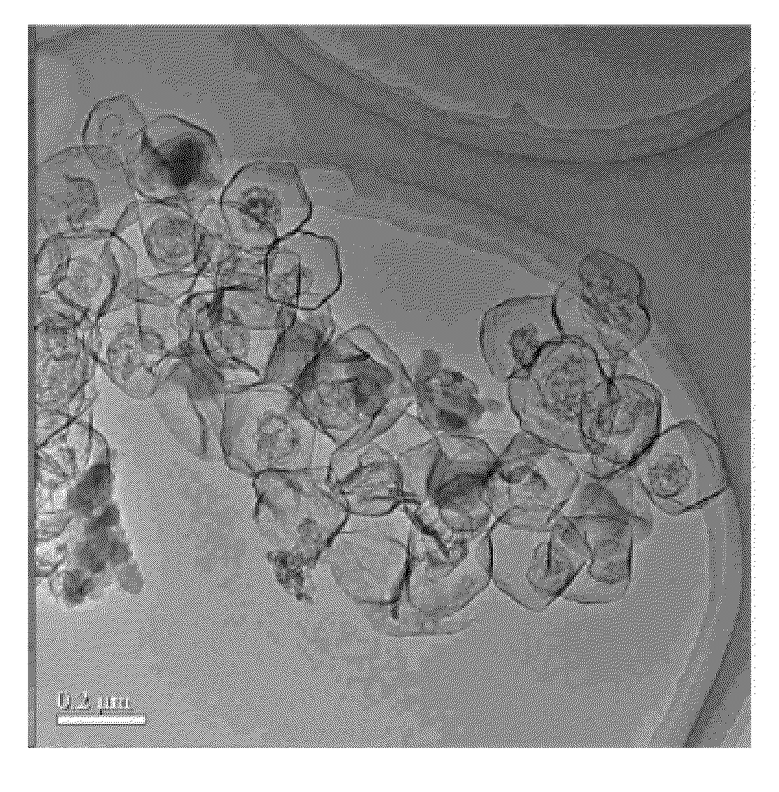
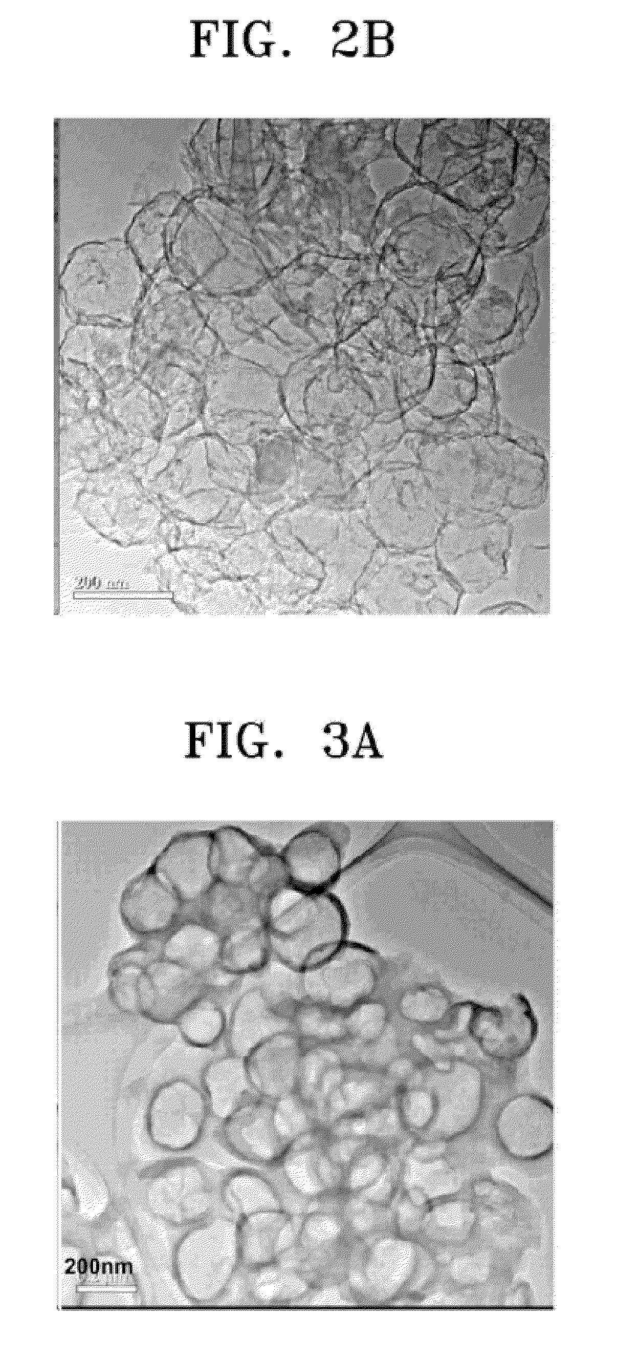
[0069]FIG. 3A and FIG. 3B are TEM photo...

example 6

[0072]0.5 g of the carbon nanosphere with at least one opening obtained in Example 1 as a carbon support was placed in a plastic bag, and then 1.9236 g of H2PtCl6 was dissolved in 1.5 mL of acetone in a beaker. The acetone solution was mixed with the carbon carrier in the plastic bag. The mixture was dried in air for 4 hours, and was then transferred to a crucible and dried in a drier at 60° C. overnight. Then, the crucible was placed in an electric furnace under nitrogen flow for 10 minutes. Next, nitrogen gas was replaced with hydrogen gas and the temperature in the electric furnace was raised from room temperature to 200° C. and maintained for 2 hours to reduce a Pt salt that was impregnated on the carbon support. The hydrogen gas was replaced with nitrogen gas and the temperature in the electric furnace was raised to 250° C. at a rate of 5° C. / min and maintained at 250° C. for 5 hours, and then cooled to room temperature. Thus, a carbon nanosphere-supported catalyst with a loadi...


PUM

PropertyMeasurementUnit
thicknessaaaaaaaaaa
diameteraaaaaaaaaa
diameteraaaaaaaaaa

Abstract

A carbon nanosphere has at least one opening. The carbon nanosphere is obtained by preparing a carbon nanosphere and treating it with an acid to form the opening. The carbon nanosphere with at least one opening has higher utilization of a surface area and electrical conductivity and lower mass transfer resistance than a conventional carbon nanotube, thus allowing for higher current density and cell voltage with a smaller amount of metal catalyst per unit area of a fuel cell electrode.

Description

CROSS-REFERENCE TO RELATED PATENT APPLICATIONS[0001]This application claims priority to and the benefit of Korean Patent Application No. 10-2004-0088218, filed on Nov. 2, 2004 in the Korean Intellectual Property Office, the disclosure of which is incorporated herein in its entirety by reference.BACKGROUND OF THE INVENTION[0002]1. Field of the Invention[0003]The present invention relates to a carbon nanosphere with at least one opening, a method of preparing the same, a supported catalyst, and a fuel cell, comprising the same. In particular, the invention relates to a carbon nanosphere with at least one opening, a method of preparing the same, a supported catalyst in which metal catalyst particles are supported on the carbon nanosphere with at least one opening, and a fuel cell that uses the supported catalyst.[0004]2. Description of the Related Art[0005]Fuel cells are clean energy sources that have received considerable interest as fossil fuels alternatives. A fuel cell is a power g...

Claims


Application Information

Patent Timeline
Patent Type & Authority Patents(United States)
IPC IPC(8): C01B31/00
CPCB01J21/18B82Y30/00C01B31/02H01M4/92H01M4/926H01M4/921H01M2008/1095Y02E60/523Y02E60/50Y10S977/888Y10S977/734Y10S977/843Y10S977/847Y10S977/737C01B32/05B82B3/0009
Inventor CHANG, HYUKPAK, CHAN-HOWANG, JIAN NONG
Owner SAMSUNG SDI CO LTD
Learn More