
Ceramic substrate for mounting a light emitting element and method for manufacturing the same

a technology of light emitting elements and ceramic substrates, which is applied in the direction of discharge tubes/lamp details, discharge tubes/solid-state device details, and discharge tubes/lamp details, etc., can solve the problems of reducing the luminance of complex light emitting elements, exposing the possibility of damage to light emitting elements, and difficult to radiate heat from light emitting elements, etc., to achieve the effect of raising the luminance of the light emitting element and suppressing damag

Inactive Publication Date: 2010-11-02
TOKUYAMA CORP
View PDF15 Cites 21 Cited by
  • Summary
  • Abstract
  • Description
  • Claims
  • Application Information

AI Technical Summary

Benefits of technology

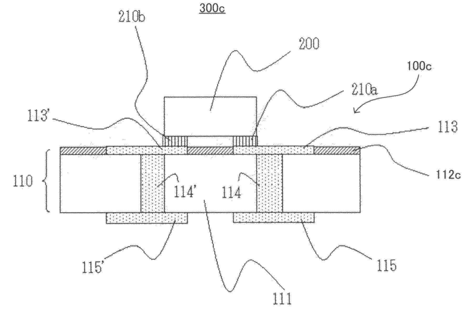
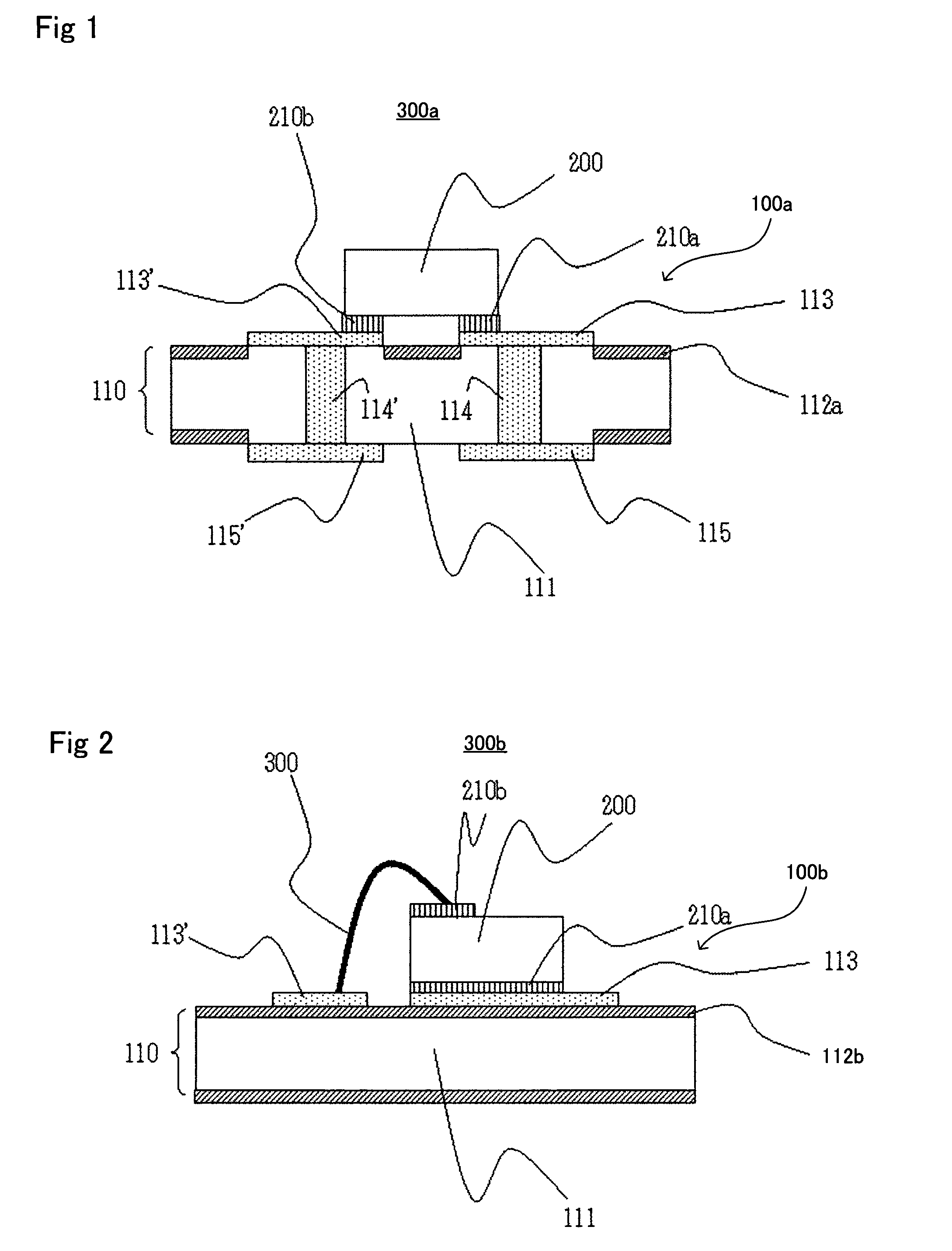
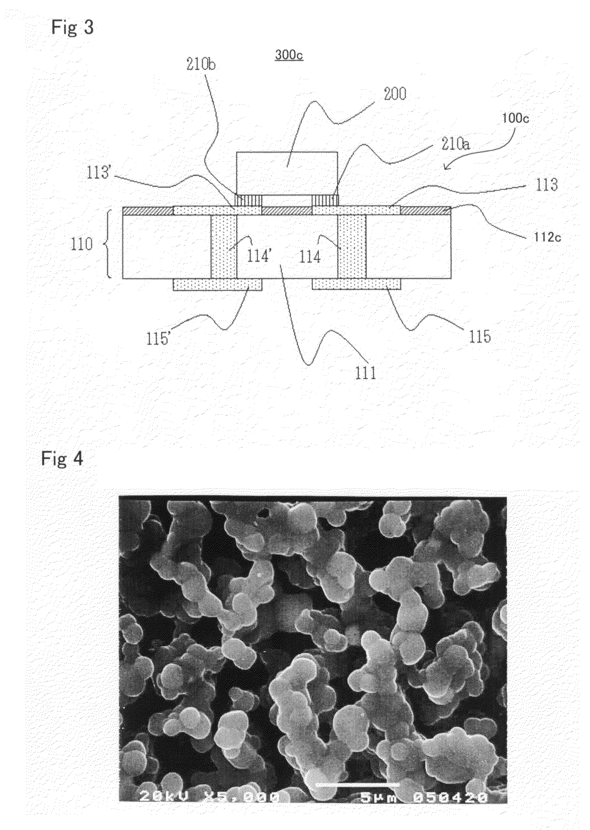
[0014]In the ceramic substrate (100) for mounting a light emitting element of the invention, since the substrate body (111) is made from a nitride ceramics, heat radiation is efficiently proceeded through the substrate and damage due to heat of the light emitting element can be perfectly suppressed. Since a surface layer portion of an exposed surface of the element placement surface side is constituted of the coat layer (112) consisting of ceramics having an optical reflectance of 50% or more for any light having wavelength of from 300 to 800 nm (such a ceramics is also referred simply as “white ceramics” for short because of being white when the ceramics has a thickness of, for example, 5 μm or more), a luminance of the light emitting element (200) can be increased.
[0070]The firing is necessary to be conducted in an atmosphere containing a reducing gas and preferably conducted in an inert gas atmosphere containing a carbon vapor as a reducing gas. If firing is conducted in an atmosphere containing no reducing gas, a light reflectance has a possibility of being low. A concentration of a reducing gas in the atmosphere, which depends on a kind of a sintering aid contained in an aluminum nitride paste, is preferably of a specific weak reducing atmosphere defined below if the sintering aid is a compound containing an alkaline earth metal. When a sintering aid is a rare earth element oxide such as yttrium oxide, it is preferable to use a specific weak reducing atmosphere or an atmosphere having a carbon vapor concentration lower than in the specific weak reducing atmosphere. When rare earth element oxide such as yttrium oxide is used as an sintering aid, there arises a possibility of reduced voids at grain boundaries and of reducing a light reflectance if firing is conducted in a atmosphere containing no reducing gas at all, which also depends on a firing temperature.

Problems solved by technology

Conventionally, a silicon substrate has been used as a submount, whereas there has been a problem that a complex light emitting element is reduced in luminance thereof since the silicon substrate absorbs light in the wavelength range of from 450 nm (blue) to 560 nm (green) emitted from an LED.
An aluminum oxide sintered body in white color of which an insulating substrate of Japanese Patent Application Laid-Open No. 2003-60243 is constituted has a property that a reflectance is 50% or more in the range of from 350 to 560 nm in wavelength, while, on the other hand, having a property of a thermal conductivity of about 20 W / m·K, which is relatively small, which makes it hard to radiate heat from the light emitting element to outside, causing a possibility of damage in the light emitting element to be revealed.

Method used


Image

  • Ceramic substrate for mounting a light emitting element and method for manufacturing the same
  • Ceramic substrate for mounting a light emitting element and method for manufacturing the same
  • Ceramic substrate for mounting a light emitting element and method for manufacturing the same

Examples


example 1

(An Example Having Used an Aluminum Nitride Substrate on a Surface of which a Coat Layer Constituted of Oxide Imparting a Surface a High Light Reflectance was Formed by Being Subjected to Sufficient Oxidation Treatment)

[0076]Mixed in a ball mill were 100 parts by mass of aluminum nitride powder, 5.0 parts by mass of yttrium oxide, 1.0 part by mass of tetraglycerine monoolate, as a surfactant; 40 parts by mass of toluene as a solvent, 13 parts by mass of poly n-butyl methacrylate as a binder, 4.2 parts by mass of dibutyl phthalate as a plasticizer, 10 parts by mass of toluene, 5 parts by mass of butyl acetate to obtain a white slurry. Then, the obtained slurry was subjected to forming into the shape of a sheet by means of a doctor blade to prepare an insulating substrate green sheet with a thickness of 0.6 mm. The obtained green sheet was heated for degreasing at 850° C. for 2 hr in a flow of hydrogen gas containing water at 10 litters / min. Note that a temperature rise rate in degrea...

example 2

(An Example Using an Aluminum Nitride Substrate on a Surface of which a Coat Layer Constituted of a White Ceramics is Coated.)

[0079]A white ceramic paste was prepared by mixing 68 parts by mass of boron nitride powder, 9 parts by mass of boron oxide powder, 23 parts by mass of aluminum nitride powder, 26 parts by mass of ethyl cellulose and 110 parts by mass of terpineol as a solvent. Then, the obtained paste was coated on one surface of an aluminum nitride green sheet adjusted in a similar way to that in Example 1 by means of a printing method to form a paste layer with a thickness of 15 μm. Thereafter, degreasing and firing were conducted in a similar way to that in Example 1 to form the coat layer (with a thickness of 10 μm) constituted of boron nitride. Note that a tone of a surface of the coat layer was of a white color. The obtained sintered body was evaluated on a reflectance for light having wave length of from 300 to 800 nm on the surface of the coat layer, a density and a ...

example 3

(An Example Using an Aluminum Nitride Substrate on a Surface of which a Coat Layer Constituted of a White Ceramics (Boron Nitride) is Coated)

[0080]A white ceramic paste was prepared in a similar way to that in Example 2 with the exception that a composition of a white ceramic paste that was used was such that 68 parts by mass of boron nitride powder, 23 parts by mass of aluminum nitride powder, 18 parts by mass of yttrium oxide, 28 parts by mass of ethyl cellulose and 120 parts by mass of terpineol (solvent), then the obtained paste was coated on a an aluminum nitride green sheet, and degreased and sintered in a similar way to that in Example 2. The obtained sintered body substrate had the coat layer (with a thickness of 10 μm) constituted of boron nitride and a tone of the coated layer was white. The obtained sintered body was evaluated on a reflectance for light having wavelength of from 300 to 800 nm on the surface of the coated layer, density and thermal conductivity in a simila...


PUM

PropertyMeasurementUnit
thermal conductivityaaaaaaaaaa
thicknessaaaaaaaaaa
optical reflectanceaaaaaaaaaa

Abstract

A ceramic substrate for mounting a light emitting element. The ceramic substrate has a placement surface for placing a light emitting element having an electrode; and an electrode electrically-connected with the electrode of the light emitting element, wherein the ceramic substrate comprises a substrate body consisting of a nitride ceramics; and a coat layer coating at least a part of a surface of the substrate body and consisting of a ceramics different from the nitride ceramics forming the substrate body; and the coat layer has an optical reflectance of 50% or more for any light having a wavelength of from 300 to 800 nm, which can increase a luminance of the light emitting element by reflecting the light emitted from the element efficiently with certainty, and which has a high heat radiation property; and a manufacturing method therefor.

Description

FIELD OF THE INVENTION[0001]The invention relates to a ceramic substrate used for mounting a light emitting element such as a light emitting diode or the like and a manufacturing method therefor.BACKGROUND ART[0002]A light emitting element has been applied in various fields because of low electrical power consumption. For example, a light emitting diode (hereinafter can be referred to as LED for short) can work not only as a monochromatic LED emitting light in red, green, blue or the like, but also as a white LED by providing a fluorescent material on a blue LED; therefore, LEDs, with the help of improvement on luminance thereof, have been widely spread in application over many fields such as a light source for an electric display board, a backlight source for a portable telephone, a personal computer and the like.[0003]An LED emitting blue light has been generally manufactured by forming an electrode for p type and an electrode for n type onto the surface of the GN-based compound s...

Claims


Application Information

Patent Timeline
Patent Type & Authority Patents(United States)
IPC IPC(8): H01L33/58H01L33/46H01L33/48H01L33/64
CPCC04B41/009C04B41/5063C04B41/5064C04B41/87H01L33/641H05K1/0274C04B41/5031C04B41/0072C04B41/4556C04B41/4539C04B41/5045C04B35/58C04B35/581H01L2224/13C04B2111/80H01L33/60H05K1/0306H05K1/181H05K2201/017H05K2201/10106H05K2201/2054H01L2224/48091H01L2224/73265H01L2224/45144H01L2924/00014H01L2924/00H01L2224/48227
Inventor MAEDA, MASAKATSUYAMAMOTO, YASUYUKI
Owner TOKUYAMA CORP
Learn More