Electrochemical element having an ellipsoidal assembly configured for high power input

a technology of ellipsoidal assembly and electrochemical element, which is applied in the direction of wound/folded electrode electrodes, cell components, sustainable manufacturing/processing, etc., can solve the problems of increased electrical loss and temperature rise during a high-rate charge/discharge, frequent short circuit, and inability to stabilize welding conditions. to achieve the effect of improving the current collection efficiency

Inactive Publication Date: 2010-07-27
PANASONIC CORP
View PDF12 Cites 13 Cited by
  • Summary
  • Abstract
  • Description
  • Claims
  • Application Information

AI Technical Summary

Benefits of technology

[0013]The present invention has been made in view of the above problems in the conventional techniques. It is an object of the present invention to provide an electrochemical element comprising a connection structure which improves the current collection efficiency from an electrode assembly.
[0015]According to the above configuration, the strip-shaped positive and negative electrodes are wound around into a flat shape to form the electrode assembly. Subsequently, the exposed current collector portion of the positive electrode protruding beyond the separator from the one end of the electrode assembly is pressed to be brought into contact with each other and welded, and the exposed current collector portion of the negative electrode protruding beyond the separator from the other end of the electrode assembly is pressed to be brought into contact with each other and welded. Therefore, the positive electrode is connected to the positive lead at a plurality of portions, and also the negative electrode is connected to the negative lead at a plurality of portions. Since current is collected from the plurality of portions of the strip-shaped positive and negative electrodes, an electrochemical element having a small internal resistance and excellent current collection efficiency is configured. Particularly, an electrical loss and a temperature increase during a high-rate charge / discharge are prevented.
[0017]According to the above configuration, the positive and negative electrodes are wound around into a flat shape to form the electrode assembly. Subsequently, the exposed current collector portion of the positive or negative electrode is pressed and welded at the one end side. Then, the positive or negative electrode is connected to the lead at a plurality of portions. Therefore, an electrochemical element having a small internal resistance and excellent current collection efficiency is configured.
[0018]In any of the above configurations, the position of the separator interposed between the positive and negative electrodes and the width of the separator are adjusted such that the edges thereof are located inside the edge of the exposed current collector portion to be pressed and welded and are located outside the edge of the electrode not to be pressed and welded. Therefore, a short-circuited between the positive and negative electrodes due to the deformation of the electrodes is prevented during pressing the exposed current collector portion.

Problems solved by technology

In this case, when only one portion of the current collector is connected to the portion serving as an external connection terminal, a current path from a distant portion in the wound strip-shaped current collector to the connected portion becomes longer, resulting in an increase in electrical loss and temperature rise during a high-rate charge / discharge.
However, in the configuration disclosed in Japanese Patent Laid-Open Publication No. 2000-294222 in which a flat surface is formed through bending a current collector protruded from an end and welded with a current collector plate placed thereon, the welding conditions cannot be stabilized when a thin electrode current collector is employed for obtaining high capacity, resulting in a frequent short circuit due to heat fusion of a separator having a poor heat resistance.
Particularly, this phenomenon often occurs in a lithium ion battery employing a thin metal foil serving as a current collector, resulting in the reduction in production yield.
However, since the winding core is required, the thickness of the battery cannot be reduced as a flat prismatic battery.
Therefore, the battery has a disadvantage when the battery is employed in an apparatus requiring downsizing or a plurality of the batteries are integrated to form a battery pack.
Therefore, the electrodes cannot be cut in an efficient manner, resulting in poor productivity.

Method used


Image

  • Electrochemical element having an ellipsoidal assembly configured for high power input
  • Electrochemical element having an ellipsoidal assembly configured for high power input
  • Electrochemical element having an ellipsoidal assembly configured for high power input

Examples


Embodiment Construction

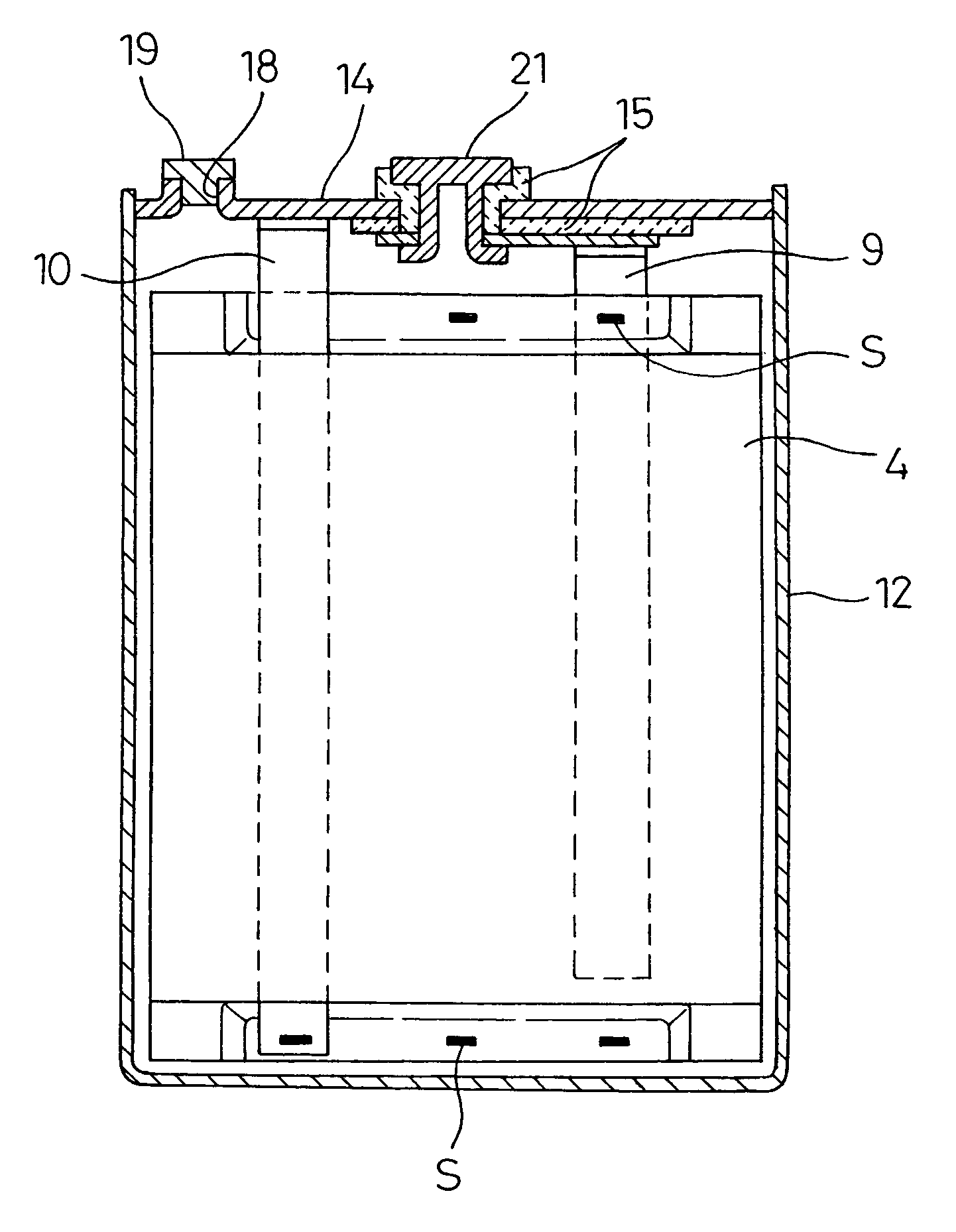
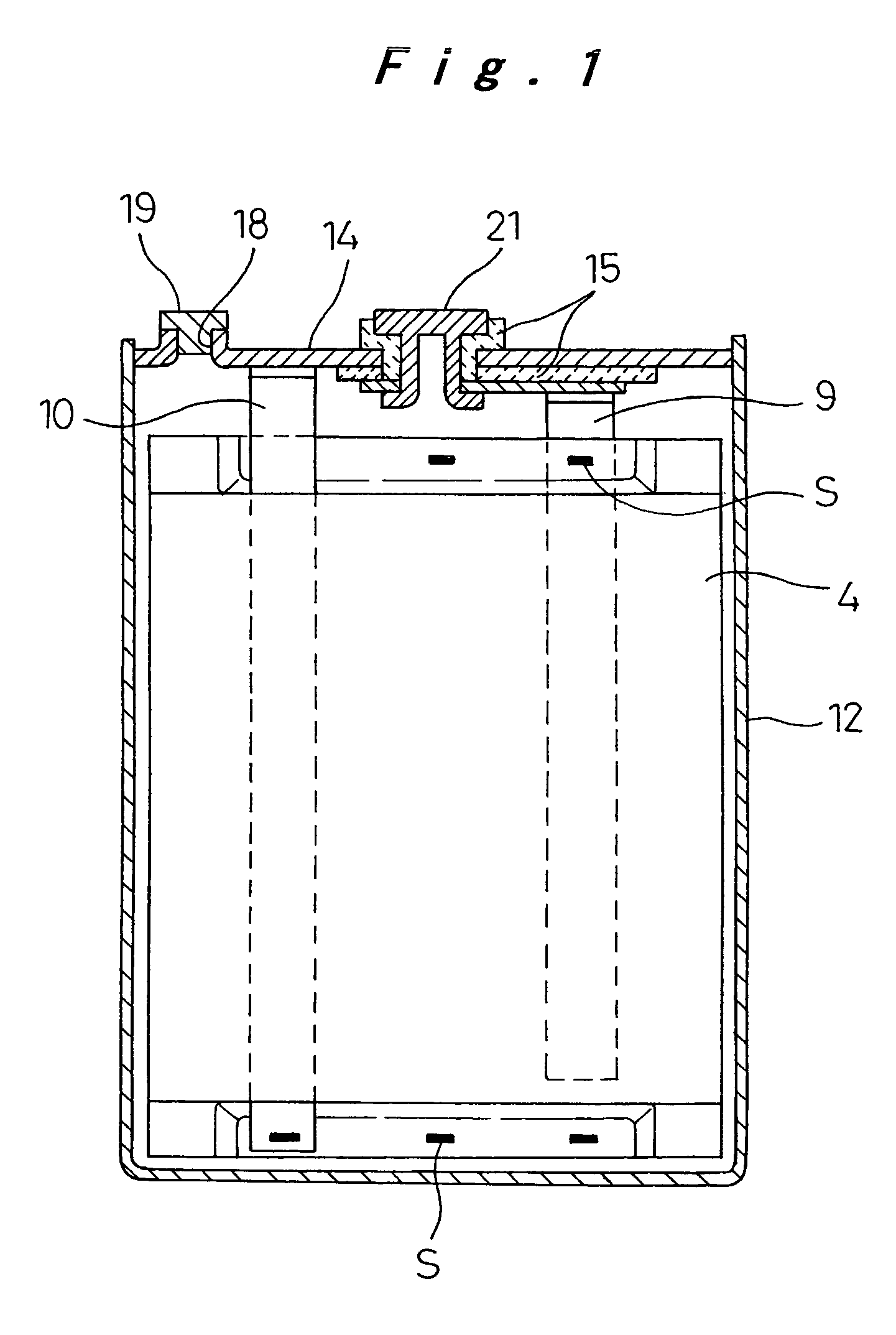
[0027]In the present embodiment, the connection structure according to the present invention is applied to a lithium ion rechargeable battery which is an example of an electrochemical element. As shown in FIG. 1, the lithium ion rechargeable battery according to the present embodiment has an outer shape of a flat prismatic shape, and comprises an electrode assembly 4 accommodated in a battery case 12. The electrode assembly 4 is formed by winding a positive electrode and a negative electrode with a separator interposed therebetween such that the cross section thereof has an ellipsoidal shape. A positive lead 9 pulled out from the positive electrode is electrically connected to an external positive connection terminal 21 provided in a sealing plate 14 which seals the opening of the battery case 12 and is insulated from the external positive connection terminal 21. A negative lead 10 is pulled out from the negative electrode and is connected to the sealing plate 14.

[0028]As shown in F...


PUM

PropertyMeasurementUnit
thicknessaaaaaaaaaa
total thicknessaaaaaaaaaa
thicknessaaaaaaaaaa

Abstract

The electrochemical element includes an electrode assembly accommodated in a case with an electrolyte. The electrode assembly is formed into a flat shape by winding positive and negative electrodes with a separator interposed therebetween. The positive electrode includes an exposed positive current collector portion uncoated with an active material and formed in one end in the width direction of a strip-shaped positive current collector, and a positive lead is attached to the exposed positive current collector portion. The negative electrode includes an exposed negative current collector portion uncoated with an active material and formed in the other end in the width direction of a strip-shaped negative current collector, and a negative lead is attached to the exposed current collector portion. The exposed positive current collector portion on the one end is pressed and welded, and the exposed negative current collector portion on the other end is pressed and welded to form the electrode assembly. This implements a current collection structure for providing stable conductive connection with high quality in a simple manner for an electrochemical element requiring high power.

Description

[0001]The present disclosure relates to subject matter contained in priority Japanese Patent Application No. 2004-175186 filled on Jun. 14, 2004, the contents of which is herein expressly incorporated by reference in its entirety.BACKGROUND OF THE INVENTION[0002]1. Field of the Invention[0003]The present invention relates to an electrochemical element such as a battery or an electric double layer capacitor having a prismatic outer shape and comprising an electrode assembly composed of positive and negative electrodes wound into a flat shape, and being accommodated into a case together with an electrolyte. In particular the invention relates to an electrochemical element having a current collection structure designed for high power output.[0004]2. Description of the Related Art[0005]In an electrochemical element such as a battery or an electric double layer capacitor, an electrode assembly having a winding structure composed of positive and negative electrodes wound with a separator ...

Claims


Application Information

Patent Timeline
Patent Type & Authority Patents(United States)
IPC IPC(8): H01M10/00H01M4/02H01M4/64H01M50/528H01G11/00H01G11/52H01G11/66H01G11/70H01G11/74H01G11/86H01M4/13H01M10/04H01M10/05H01M10/0525H01M10/0566H01M10/0587H01M50/536H01M50/538
CPCH01M2/263H01M4/13H01M10/0431H01M10/0587H01M10/0525Y02E60/122Y02T10/7011Y02E60/10H01M50/538Y02P70/50H01M50/536
Inventor KOZUKI, KIYOMI
Owner PANASONIC CORP
Why Eureka
Try Eureka