
Rechargeable battery having current collecting plates coupled with uncoated regions of electrodes

a rechargeable battery and current collecting technology, applied in the direction of wound/folded electrode electrodes, cell components, sustainable manufacturing/processing, etc., can solve the problems of high power output, inefficient structure that collects current using leads, and difficult manufacturing of rechargeable batteries, etc., to achieve uniform output of current, improve current collection efficiency, and enhance power output performance

Inactive Publication Date: 2010-08-24
SAMSUNG SDI CO LTD
View PDF13 Cites 6 Cited by
  • Summary
  • Abstract
  • Description
  • Claims
  • Application Information

AI Technical Summary

Benefits of technology

[0013]The present invention provides a rechargeable battery that has an improved current collecting efficiency to enhance power output performance and evenly output the current that is generated in every part of an electrode assembly.

Problems solved by technology

However, a structure that collects current using leads is inefficient in a large-size battery that requires high power output.
In addition, the above-described structure has difficulty in evenly outputting the current that is generated in every part of the electrode assembly when it is used in the large-sized battery.
This rechargeable battery is difficult to manufacture because a plurality of leads are fixed in the lead adhesion region.
Also, since an active material is not present inside the cell, the capacity of the portion that does not participate in the reaction, that is, the portion occupied by the lead adhesion regions and the leads, becomes large, which makes it hard to form a large-size high-power battery.
The technology, however, cannot maximize the current collecting efficiency because the contact area of the unit that substantially connects the projecting ends to the terminals electrically is restrictive.

Method used


Image

  • Rechargeable battery having current collecting plates coupled with uncoated regions of electrodes
  • Rechargeable battery having current collecting plates coupled with uncoated regions of electrodes
  • Rechargeable battery having current collecting plates coupled with uncoated regions of electrodes

Examples


Embodiment Construction

[0022]A rechargeable battery comprising the current collecting plates of the present invention may maximize the contact area of the current collecting plates to the uncoated regions of the electrode assembly, thus improving the current collecting efficiency. In addition, the battery may evenly output the current that is generated in every part of the electrode assembly.

[0023]The rechargeable battery of the present invention may be used as an energy source a motor for hybrid electric vehicles (HEV), electric vehicles (EV), wireless appliances, motorcycles, motor scooters and the like which require high power performance and large capacity.

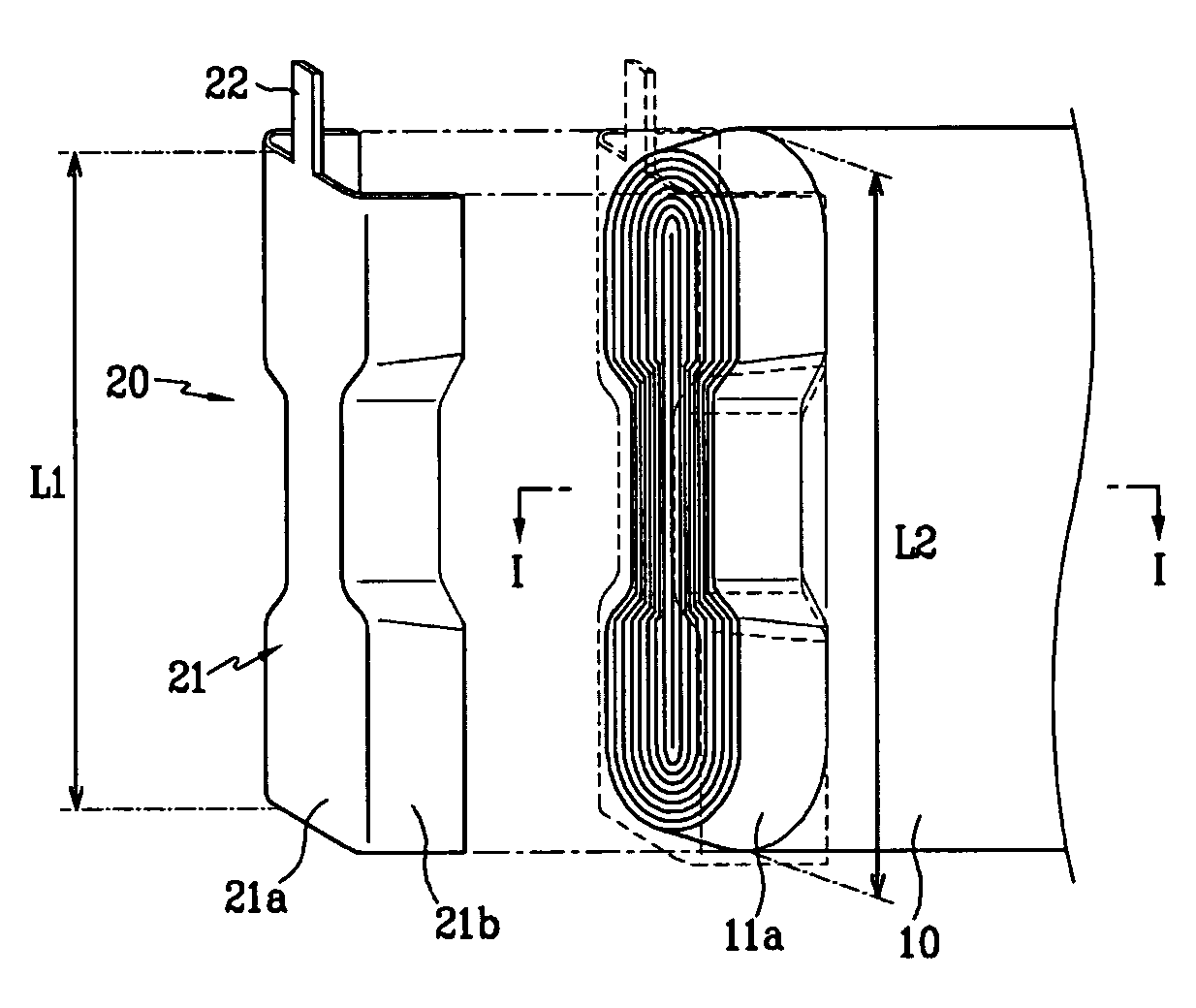
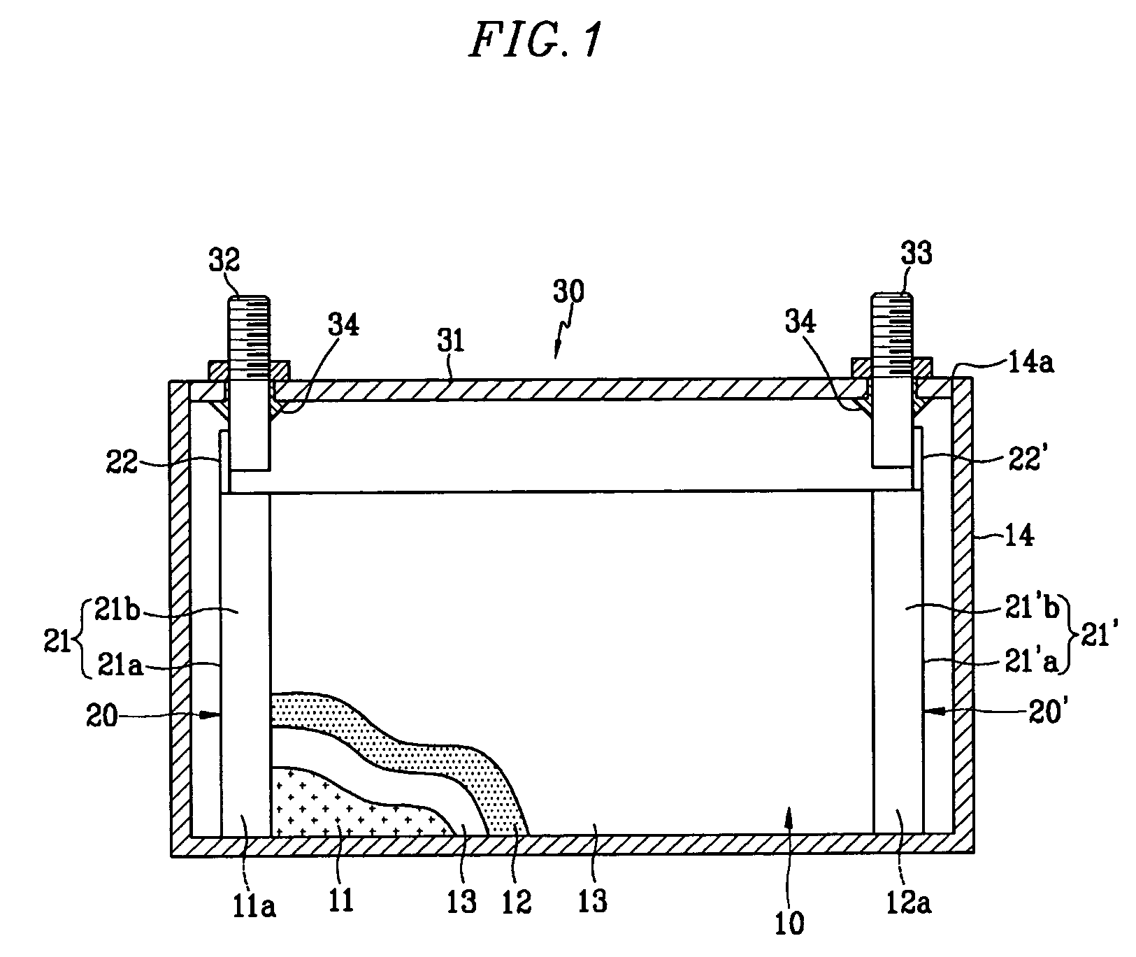
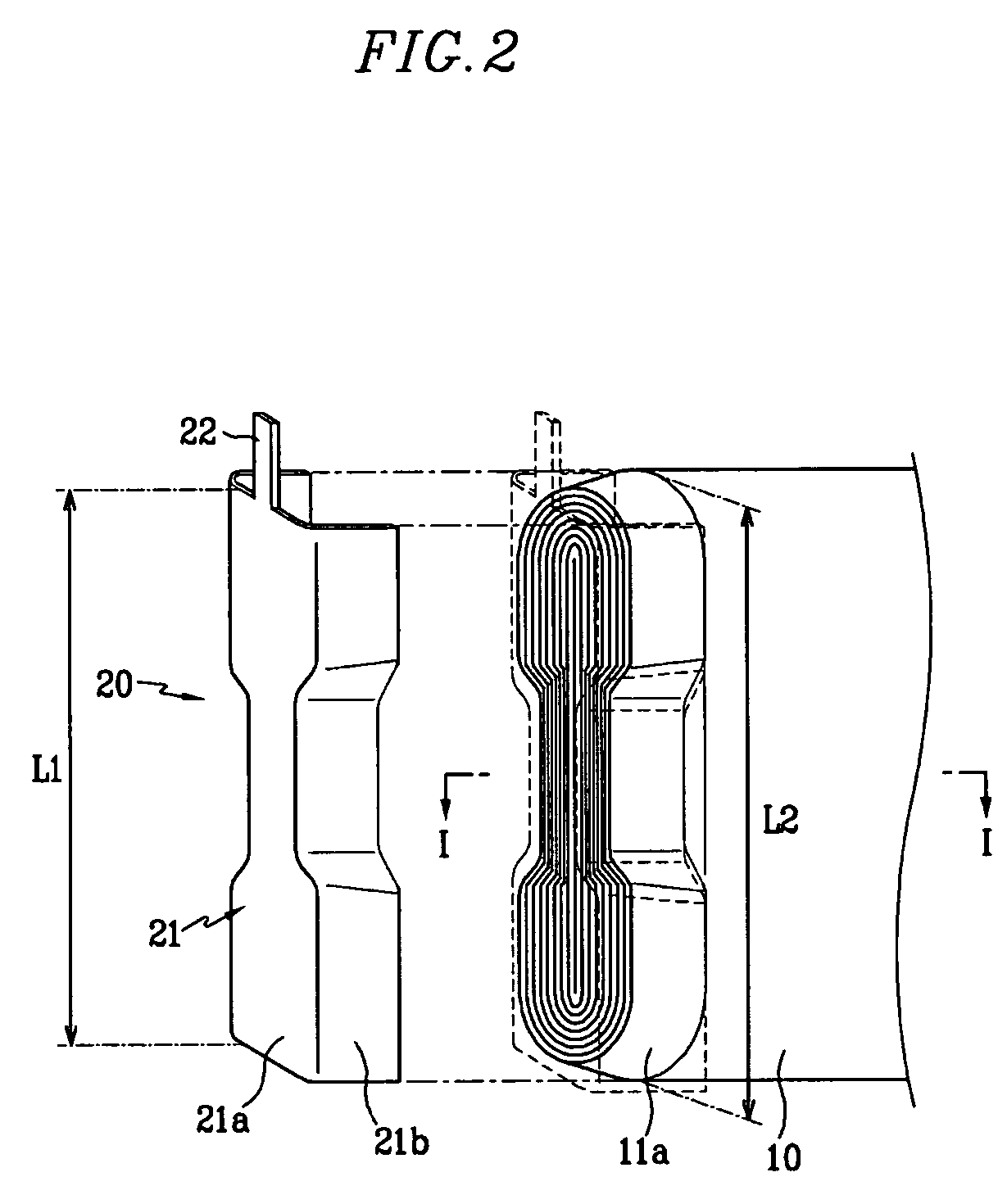
[0024]FIG. 1 is a cross-sectional view of a rechargeable battery according to an exemplary embodiment of the present invention. As shown in FIG. 1, the rechargeable battery includes an electrode assembly 10 that is formed by stacking a band-type positive electrode 11 and a band-type negative electrode 12 with a separator 13 interposed between them a...


PUM

PropertyMeasurementUnit
shapeaaaaaaaaaa
current collecting efficiencyaaaaaaaaaa
power storage capacityaaaaaaaaaa

Abstract

A rechargeable battery includes an electrode assembly comprising a positive electrode that has an uncoated region that is not coated with an active material along an edge, a negative electrode that has an uncoated region that is not coated with an active material along an edge, and a separator that is placed between the positive electrode and the negative electrode. The battery further comprises current collecting plates that are joined with the uncoated regions of the positive electrode and negative electrode while covering the uncoated regions, a case for housing the electrode assembly and the current collecting plates, and a cap assembly that is coupled with the case to seal it and includes terminals that are coupled with the current collecting plates.

Description

CROSS REFERENCE TO RELATED APPLICATION[0001]This application claims priority to and the benefit of Korean patent application No. 10-2004-0047015 filed in the Korean Intellectual Property Office on Jun. 23, 2004, the entire disclosure of which is incorporated herein by reference.BACKGROUND OF THE INVENTION[0002]1. Field of the Invention[0003]The present invention relates to a rechargeable battery that has improved current collecting efficiency.[0004]2. Background of the Invention[0005]Unlike a nonrechargeable battery that may not be recharged, a rechargeable battery may be charged and discharged repeatedly. A lithium rechargeable battery may be packaged into a pack shape to be used as a power source for various portable electronic devices such as cellular phones, laptop computers, and camcorders.[0006]Recently, rechargeable batteries with high power storage capacity have been developed for use as power sources for driving motors such as those in hybrid automobiles.[0007]These recharg...

Claims


Application Information

Patent Timeline
Patent Type & Authority Patents(United States)
IPC IPC(8): H01M2/28H01M2/08H01M10/38H01M50/541H01M4/70H01M4/74H01M10/04H01M50/10H01M50/103H01M50/533H01M50/536H01M50/538
CPCH01M2/263H01M4/742H01M4/70H01M2002/0205Y02E60/10H01M50/538Y02P70/50H01M50/103H01M50/536H01M50/533H01M10/0431
Inventor CHO, KYU-WOONGLIM, HONG-SUP
Owner SAMSUNG SDI CO LTD
Learn More