
Anode supported solid oxide fuel cell

a solid oxide fuel cell and anode support technology, applied in the direction of solid electrolyte fuel cells, fuel cells, cell components, etc., can solve the problems of high operation temperature of the solid oxide fuel cell, damage to deterioration of the performance of the fuel cell, so as to reduce the loss of electrons, increase the contact surface, and increase the current collecting efficiency

Inactive Publication Date: 2009-02-05
KOREA ADVANCED INST OF SCI & TECH
View PDF4 Cites 5 Cited by
  • Summary
  • Abstract
  • Description
  • Claims
  • Application Information

AI Technical Summary

Benefits of technology

[0013]It is an object of the present invention to provide a solid oxide fuel cell in which an anode is formed with a current collecting hole and a current collecting member is inserted into the current collecting hole so as to rapidly collect the generated electrons and thus reduce a loss of the electrons, and also a current collecting layer connected with the current collecting member is formed at an outer surface of the anode so as to increase a contact surface, thereby increasing the current collecting efficiency.
[0014]It is another object of the present invention to provide a solid oxide fuel cell in which the anode is further formed with a reinforcement hole and a reinforcement member is inserted in the reinforcement hole, thereby improving a cell strength.

Problems solved by technology

Particularly, the SOFC has a disadvantage that its operation temperature is high, but also has an advantage that it can be used for large scale power generation.
But if a thickness of the anode is increased in order to solve the problem, gas diffusion is deteriorated, and thus a performance of the fuel cell is also deteriorated.
Particularly, the performance of the fuel cell is damaged in a high current range.
Further, according as the reaction is processed, a gas diffusion path is clogged by carbon deposition.
Since it makes difficult to collect current generated from the anode, there is a problem of electric power loss.

Method used


Image

  • Anode supported solid oxide fuel cell
  • Anode supported solid oxide fuel cell
  • Anode supported solid oxide fuel cell

Examples


Embodiment Construction

[0032]100: solid oxide fuel cell (SOFC)[0033]10: electrolyte layer[0034]20: anode[0035]21: current collecting hole[0036]22: current collecting member[0037]23: current collecting layer[0038]24: reinforcement hole[0039]25: reinforcement member[0040]30: cathode

BEST MODE FOR CARRYING OUT THE INVENTION

[0041]Practical and presently preferred embodiments of the present invention are illustrative with reference to the accompanied drawings.

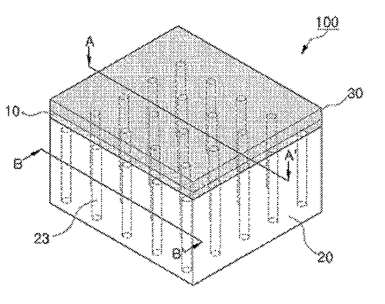
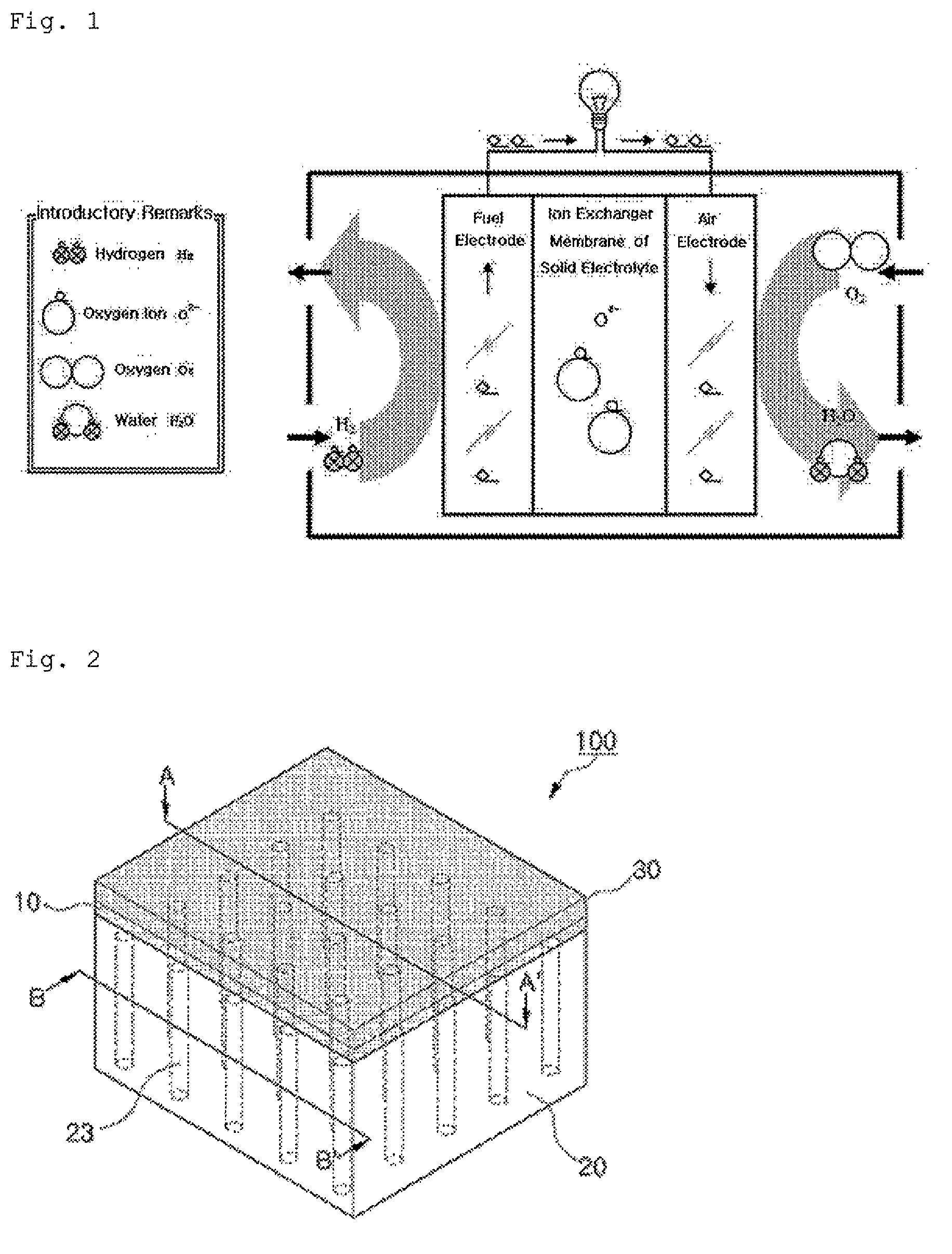
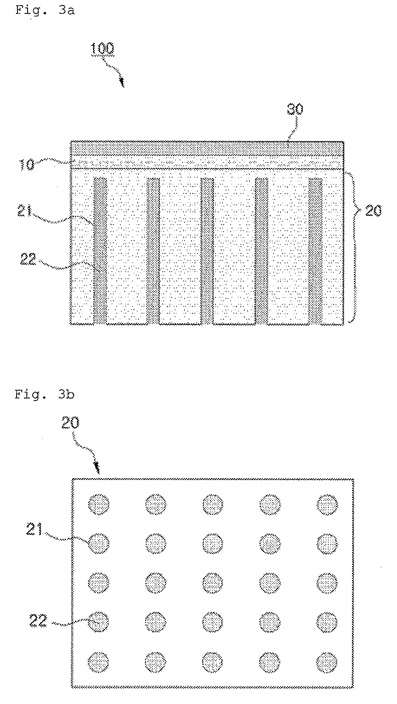
[0042]FIG. 2 is a perspective view of an SOFC according to an embodiment of the present invention, FIG. 3a is a cross-sectional view taken along a line A-A′ of FIG. 2, and FIG. 3b is a cross-sectional view taken along a line B-B′ of FIG. 2.

[0043]As shown in FIGS. 2 to 3b, the SOFC 100 includes an electrolyte layer 10, an anode 20 and a cathode 30, and the anode 20 is formed with a current collecting hole 21, and a current collecting member 22 is inserted into the current collecting hole 21.

[0044]The anode 20 and the cathode 30 are formed to be contacted wi...


PUM

PropertyMeasurementUnit
currentaaaaaaaaaa
current collecting efficiencyaaaaaaaaaa
strengthaaaaaaaaaa

Abstract

The present invention relates to a solid oxide fuel cell in which an anode is formed with a current collecting hole and a reinforcement hole, and a current collecting member and a reinforcement member are respectively in the current collecting hole and reinforcement hole, thereby increasing a current collecting efficiency and thus an efficiency of producing electric energy and also improving a cell strength. The solid oxide fuel cell has an electrolyte layer; an anode and a cathode formed to be contacted with both surfaces of the electrolyte layer; a current collecting hole formed in the anode; and a current collecting member inserted into the current collecting hole.

Description

TECHNICAL FIELD[0001]The present invention relates to a solid oxide fuel cell (SOFC), and more particularly, to a solid oxide fuel cell in which an anode is formed with a current collecting hole and a reinforcement hole, and a current collecting member and a reinforcement member are respectively in the current collecting hole and reinforcement hole, thereby increasing a current collecting efficiency and thus an efficiency of producing electric energy and also improving a cell strength.BACKGROUND ART[0002]A fuel cell, which directly converts chemical energy generated by oxidation into electrical energy, is a new green futuristic energy technology which can generates the electrical energy from materials such as oxygen, hydrogen and the like which is found in abundance on the earth.[0003]In the fuel cell, oxygen is supplied to a cathode and hydrogen is supplied to an anode so that an electrochemical reaction is performed in a reverse way of water electrolysis so as to generate electric...

Claims


Application Information

Patent Timeline
Patent Type & Authority Applications(United States)
IPC IPC(8): H01M8/10
CPCH01M4/8605H01M8/1213Y02E60/525H01M2008/1293Y02E60/521H01M2004/8684Y02E60/50H01M8/02H01M8/12
Inventor BAE, JOONGMYEONBAEK, SEUNG-WOOK
Owner KOREA ADVANCED INST OF SCI & TECH
Learn More