Integrated scanning probe microscope and confocal microscope
a scanning probe and microscope technology, applied in the field of scanning probe microscopes, can solve the problems of limited resolution in the x and y axes to that of normal optical microscopes, and not solve the problems of scan speed and field of view completely, and achieve the effect of reducing scan times
- Summary
- Abstract
- Description
- Claims
- Application Information
AI Technical Summary
Benefits of technology
Problems solved by technology
Method used
Image


Examples
first embodiment
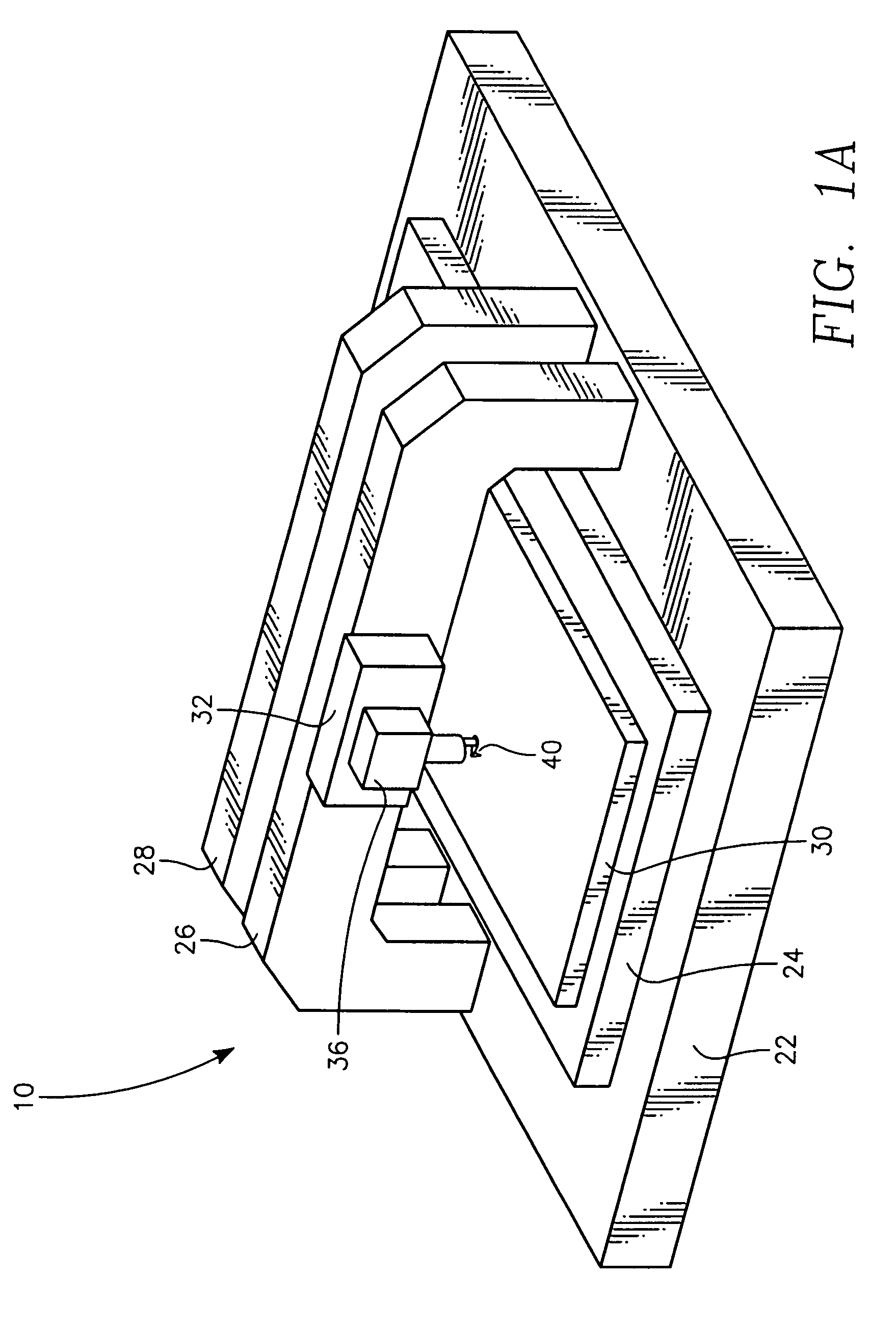
[0061]FIG. 1A is a perspective view of the invention. Combined microscope system 10 has a base 22 that is typically made of precision finished granite. Granite is preferred because it can be cut and surface ground to a high degree of flatness and smoothness although other stable precision shaped material such as certain glasses like Zerodur available from Schott Glass Technologies or ceramics may also be used. A long range X, Y stage 24 is affixed to granite base 22. A sample 30 to be observed and measured is carried by stage 24. In this embodiment a first bridge 26 carries a long range Z axis stage 32 that in turn carries a scanning probe microscope 36. Second bridge 28 is visible in this view and will presently be described in greater detail.
[0062]FIG. 1B shows the first embodiment in a side view. In this view of microscope system 10, second bridge 28 is shown as a support for a second large range Z axis stage 34. Stage 34 in turn supports a confocal microscope 38. A computer 50 s...
second embodiment
[0066]FIG. 1C shows a second embodiment in a side view. This is a view of a single bridge combined scanning probe and confocal microscope system 20.
[0067]A bridge 26 is shown as a support for first and second large range Z axis stages 32 and 34. Stage 32 supports probe microscope 36 and stage 34 supports confocal microscope 38. Computer 50 sends commands to, and receives data from, confocal microscope 38, and probe microscope 36. Computer 50 also processes data and presents image data to the user either through display device 52 or to second computer and display (not shown) via networking cables (not shown). Computer 50 also sends commands to long range Z axis stages 32 and 34 as well as sending commands to long range X, Y stage 24. As in the first embodiment confocal microscope 38 has an objective lens 42.
[0068]In operation the combined microscope system 20 allows the sample to be located below confocal microscope 38 for observation. Confocal microscope 38 has a wide field of view ...
third embodiment
[0071]FIG. 3 shows the present invention. A combination confocal and probe microscope system 60 includes confocal microscope 38 comprising a detector assembly 62 and an objective lens 64 and a first alternate probe microscope 70. A probe microscope frame 66, shown in section view, is positioned near but not touching objective lens 64. Probe microscope 70 comprises an X, Y scanning translator 68, shown in section view, that creates relative X, Y motion between frame 66 and probe module 71. Such translator 68 may be a piezo driven flexure. Module 71 carries a light source 72 that is typically a laser or a diode laser. Light source 72 creates a light beam 74 directed toward a cantilever 84. The reflection of light beam 72 is then directed through a detector lens 82 and then onto a photo-diode array 76. Cantilever 84 is connected to probe assembly 80 that is in turn connected to Z motion device 78.
[0072]In operation X, Y flexure 68 moves first alternate probe microscope 70 in X, and Y p...
PUM
 Abstract
Description
Claims
Application Information
 - R&D
- Intellectual Property
- Life Sciences
- Materials
- Tech Scout
- Unparalleled Data Quality
- Higher Quality Content
- 60% Fewer Hallucinations
Browse by: Latest US Patents, China's latest patents, Technical Efficacy Thesaurus, Application Domain, Technology Topic, Popular Technical Reports.
© 2025 PatSnap. All rights reserved.Legal|Privacy policy|Modern Slavery Act Transparency Statement|Sitemap|About US| Contact US: help@patsnap.com