
System and method for accelerated magnetic resonance parallel imaging

a magnetic resonance parallel imaging and parallel imaging technology, applied in the field of magnetic resonance imaging, can solve the problems of difficult and/or time-consuming to obtain accurate sensitivity maps, high net acceleration factors are not known to be implementable, and it is difficult to achieve the effect of undersampling or “acceleration” benefits, so as to reduce the total data acquisition and reduce the scan tim

Active Publication Date: 2008-12-11
THE BOARD OF TRUSTEES OF THE LELAND STANFORD JUNIOR UNIV +1
View PDF12 Cites 44 Cited by
  • Summary
  • Abstract
  • Description
  • Claims
  • Application Information

AI Technical Summary

Benefits of technology

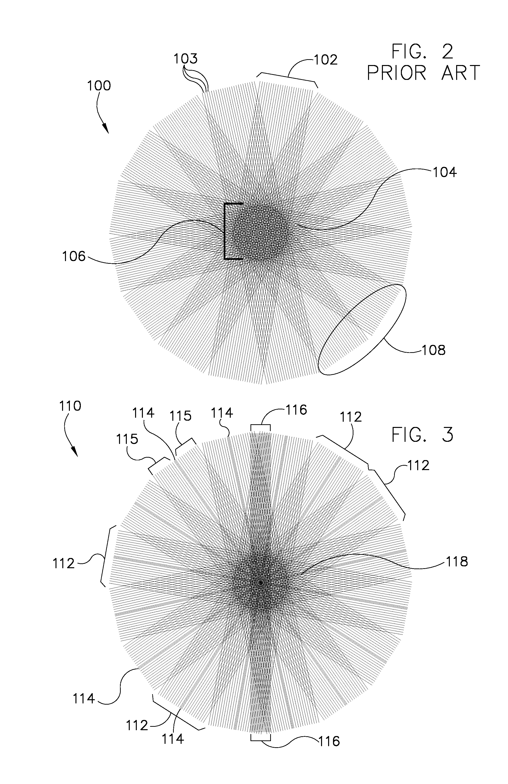
[0008]Embodiments of the present invention provide a system and method for parallel imaging in which separate calibration data need not be acquired for each set of k-space data in a segmented k-space data acquisition. For example, a blade of k-space data may utilize calibration data acquired from another blade, to reduce total data acquisition and decrease scan time.

Problems solved by technology

However, when certain imaging sequences are performed via a parallel imaging system, it can be difficult to achieve these undersampling or “acceleration” benefits.
As an example, for the PROPELLER technique, in which k-space blades are acquired at various angles rotated about the k-space center, high net acceleration factors are presently not known to be implementable.
While parallel imaging can shorten the echo train length, increase blade width, or reduce the number of acquired blades, these advantages are counterbalanced by several factors.
In techniques which use externally-determined sensitivity data, it can be difficult and / or time-consuming to obtaining accurate sensitivity maps, especially where subject motion is an issue.
For autocalibrating techniques, however, the increase in scan time when separate calibration data is acquired for each blade can significantly reduce the net acceleration provided by parallel imaging.

Method used


Image

  • System and method for accelerated magnetic resonance parallel imaging
  • System and method for accelerated magnetic resonance parallel imaging
  • System and method for accelerated magnetic resonance parallel imaging

Examples


Embodiment Construction

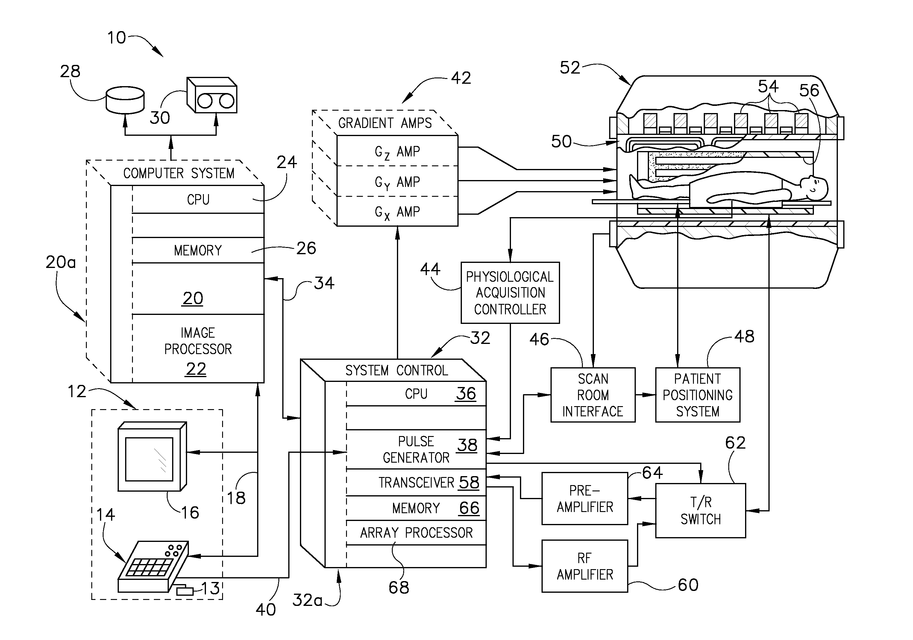
[0022]Referring to FIG. 1, the major components of a preferred magnetic resonance imaging (MRI) system 10 incorporating an embodiment of the present invention are shown. The operation of the system is controlled from an operator console 12 which includes a keyboard or other input device 13, a control panel 14, and a display screen 16. The console 12 communicates through a link 18 with a separate computer system 20 that enables an operator to control the production and display of images on the display screen 16. The computer system 20 includes a number of modules which communicate with each other through a backplane 20a. These include an image processor module 22, a CPU module 24 and a memory module 26, known in the art as a frame buffer for storing image data arrays. The computer system 20 is linked to disk storage 28 and tape drive 30 for storage of image data and programs, and communicates with a separate system control 32 through a high speed serial link 34. The input device 13 c...


PUM


Abstract

A system and method for MR imaging includes the use of a form of autocalibrated parallel imaging. By combining a segmented, rotated acquisition trajectory with autocalibration parallel imaging (API), the system and method can achieve improved motion insensitivity while maintaining the benefits of accelerated acquisition due to parallel imaging. In various embodiments, calibration values from a set of reference data or from another set of imaging data can be used in determining reconstruction weights for a given k-space data set. Thus, separate calibration data need not necessarily be acquired for each set of imaging data.

Description

BACKGROUND OF THE INVENTION[0001]The present invention relates generally to magnetic resonance imaging, and, more particularly, to a system and method for parallel imaging with segmented, accelerated acquisition. Embodiments of the system and method may utilize segmented, rotated, and / or non-Cartesian k-space trajectories such as the Periodically Rotated Overlapping Parallel Lines with Enhanced Reconstruction (PROPELLER) technique to acquire multi-channel blades of k-space data. Oversampled “calibration” regions of the blades, or of a reference blade, may then be used to determine the parallel imaging reconstruction weights, used for synthesis of additional k-space data points.[0002]MR imaging in general is based upon the principle of nuclear magnetic resonance. When a substance such as human tissue is subjected to a uniform magnetic field (polarizing field B0), the individual magnetic moments of the spins in the tissue attempt to align with this polarizing field, but precess about ...

Claims


Application Information

Patent Timeline
Patent Type & Authority Applications(United States)
IPC IPC(8): G01R33/561
CPCG01R33/4824G01R33/561G01R33/5611G01R33/565G01R33/56509G01R33/5676
Inventor BEATTY, PHILIP JAMESBRAU, ANJA C. S.
Owner THE BOARD OF TRUSTEES OF THE LELAND STANFORD JUNIOR UNIV
Learn More