
Energy invest and profit recovery systems

a technology of energy investment and profit recovery, applied in the field of electrical energy generation, can solve the problems of essentially no useful work, often wasted energy of combustion, optimistically misleading, etc., and achieve the effect of reducing energy received and magnetic permitivity

Inactive Publication Date: 2009-11-10
GIMLAN GIDEON
View PDF3 Cites 40 Cited by
  • Summary
  • Abstract
  • Description
  • Claims
  • Application Information

AI Technical Summary

Benefits of technology

"The invention provides a method for capturing and converting wasted electrical energy into useful electrical energy. The method involves temporarily condensing electrical charges and magnetic flux flows, then decondensing them using external energy sources. The decondensed energy can then be directed to a profit energy collector. The method can be used in various applications such as air conditioning systems, refrigerators, and power generation. It can also be integrated into existing systems such as compressors, fluid condensers, and heat radiators. The invention provides a way to capture and utilize otherwise wasted energy, improving efficiency and reducing environmental impact."

Problems solved by technology

Were it not for the piston chamber guiding the explosive energy of combustion in a particular direction so as to do useful work, the explosive release of combustion energy would preferentially expand randomly in all directions and do essentially no useful work.
Much of the energy of combustion is often wasted.
As poor as this number is, it is optimistically misleading.
The problem is that the released energy is allowed to rapidly dissipate and spatially distribute out into the ambient atmosphere as waste heat rather than being further guided and controlled in a manner similar to how it was controlled inside the piston chamber.
The unguided dissipation of heat does not do much useful work.
Doing so economically is the problem.
These are expensive and have low efficiencies.
This can have significant impact on the environment, particularly in times when global warming and air pollution are problems and fossil fuels or grid-supplied electrical energy are expensive.

Method used


Image

  • Energy invest and profit recovery systems
  • Energy invest and profit recovery systems
  • Energy invest and profit recovery systems

Examples


embodiment 200

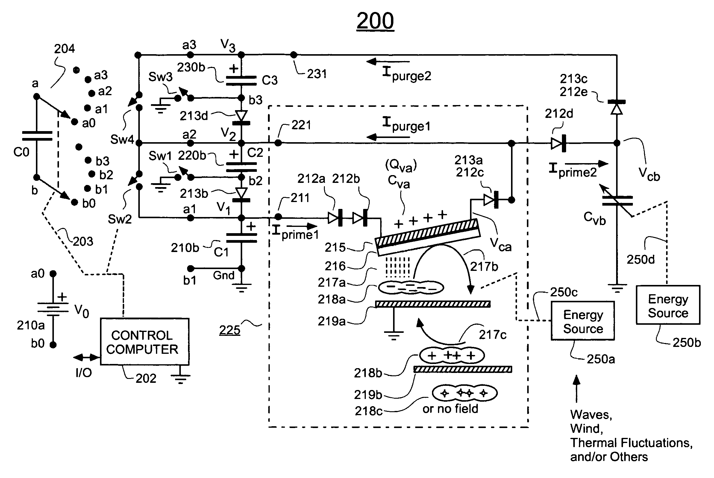
[0071]In the illustrated embodiment 200, the series combination of C1 and C2 are structured to serve as a bootstrapped charge source for investing higher voltage charge into a second variable capacitor means Cvb. Diodes 212c-212d conduct the second priming current (Iprime2) into the second variable capacitor, Cvb. Diodes 213c-213d conduct the second purging current (Ipurge2) out of capacitor Cvb and through collecting capacitor C3 (230b). Note that Ipurge2 will also flow through collecting capacitor C2 (220b). When V2cb3, then both of diode sets 212c-212d and 213c-213d will be reverse biased. Invested charge, Qvb will be temporarily trapped in variable capacitor means Cvb. It is during this latter time that the invested charge, Qvb rides up a potential energy slope to acquire its increased amount of energy. Energy source 250b provides that increasing energy via coupling 250d. The coupled energy 250d may be in dynamic mechanical form, in dynamic thermal form and / or in other form as m...

embodiment 400

[0104]Referring to FIG. 4B, a specific embodiment 400′ of a spider buoy is schematically shown in greater detail. A transparent top dome 404 is provided in a central part or other of the spider for passing solar radiation (e.g., 403a) from the Sun 403. The dome 404 may be made of hydrophobically coated glass, acrylic, etc. A spherically shaped and generally opaque bottom support (e.g., made of an aluminum copper alloy) 451 is provided under the dome and has an inner reflective surface 406 that is covered by thermally insulative but transparent material (i.e. porous glass capped at its top surface with nonporous glass). The spherical shape gives the support 451 mechanical strength, but if desired, internal reflecting surfaces 406 may be polished Fresnel style in the interior surface of the spherical shape to define a parabolic type of reflecting means that focuses reflected radiation on a dome-top, small mirror 407. The dome-top mirror 407 redirects the once-reflected solar radiation...


PUM

PropertyMeasurementUnit
voltagesaaaaaaaaaa
relative dielectric constantaaaaaaaaaa
dielectric constantaaaaaaaaaa

Abstract

A variable density actualizing means is provided for supporting one or both of temporarily condensed electric charge and intensified magnetic flux flow and for thereby generating electrical energy. More specifically, such an actualizing means comprises: (a) condensing means for condensing one or more of an amount of electrical charge supplied from a charge donating source and flux flow induced by a magnetic field generated by a magnetic field source; (b) decondensing means, integrated with the condensing means and couplable to one or more energy sources, for reducing the density of (decondensing) the charge and / or flux flow condensed by the condensing means, the decondensing being powered by input energy received from one or more of the energy sources; wherein the decondensing means is powered by at least one of (b.1) heat energy received from one or more of the energy sources; (b.2) pressure energy received from one or more of the energy sources; (b.3) displacement energy received from one or more of the energy sources; (b.4) electrolytic ion removal energy received from one or more of the energy sources; (b.5) dielectric constant reducing energy received from one or more of the energy sources; and (b.6) magnetic permitivity reducing energy received from one or more of the energy sources. The variable density actualizing means of one embodiment is provided as an integral part of a compressor of compressible fluids (i.e., refrigerants). The variable density actualizing means of one embodiment is provided as an integral part of a fluid condenser and / or heat radiator.

Description

FIELD OF DISCLOSURE[0001]The present disclosure of invention relates generally to generation of electrical energy by separation of opposed charges from one another. More specifically, it relates to the purposeful condensing of un-neutralized electrical charge, and / or the purposeful condensing of magnetic flux flow, this being followed by opportunistic decondensing of one or both of these condensed entities and by directed extraction of electrical energy from an EMF that is generated by the decondensing step.CROSS REFERENCE TO CO-OWNED APPLICATION[0002]The following copending U.S. patent application is owned by the owner of the present application, and its disclosure is incorporated herein by reference:[0003](A) Ser. No. 10 / 233,815 filed Sep. 3, 2002 by Gideon Gimlan and which is originally entitled, ELECTROSTATIC ENERGY GENERATORS AND USES OF SAME; subsequently issued as U.S. Pat. No. 6,936,994 on Aug. 30, 2005.DESCRIPTION OF RELATED ART[0004]Under well-known laws of thermodynamics,...

Claims


Application Information

Patent Timeline
Patent Type & Authority Patents(United States)
IPC IPC(8): H01M10/46
CPCH01G5/012H01M16/003H01G5/0132Y02E60/50
Inventor GIMLAN, GIDEON
Owner GIMLAN GIDEON
Learn More