Integrated circuit, semiconductor device comprising the same, electronic device having the same, and driving method of the same
a technology of integrated circuits and drives, which is applied in the direction of identification means, instruments, transistors, etc., can solve the problems of difficult to obtain a material having a drastically low dielectric constant, high cost per bit, so as to reduce the occupying area and increase the memory capacity of the dram
- Summary
- Abstract
- Description
- Claims
- Application Information
AI Technical Summary
Benefits of technology
Problems solved by technology
Method used
Image
Examples
embodiment 1
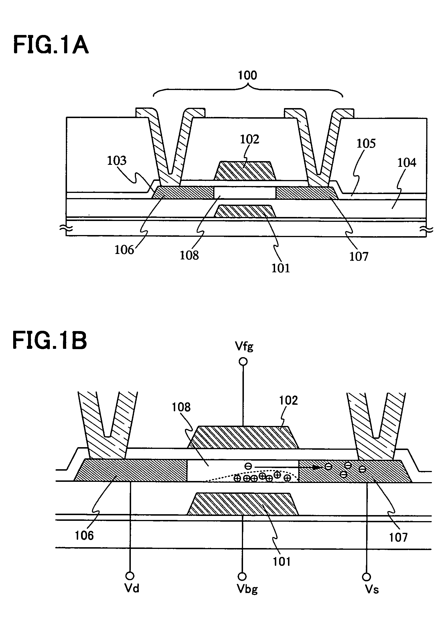
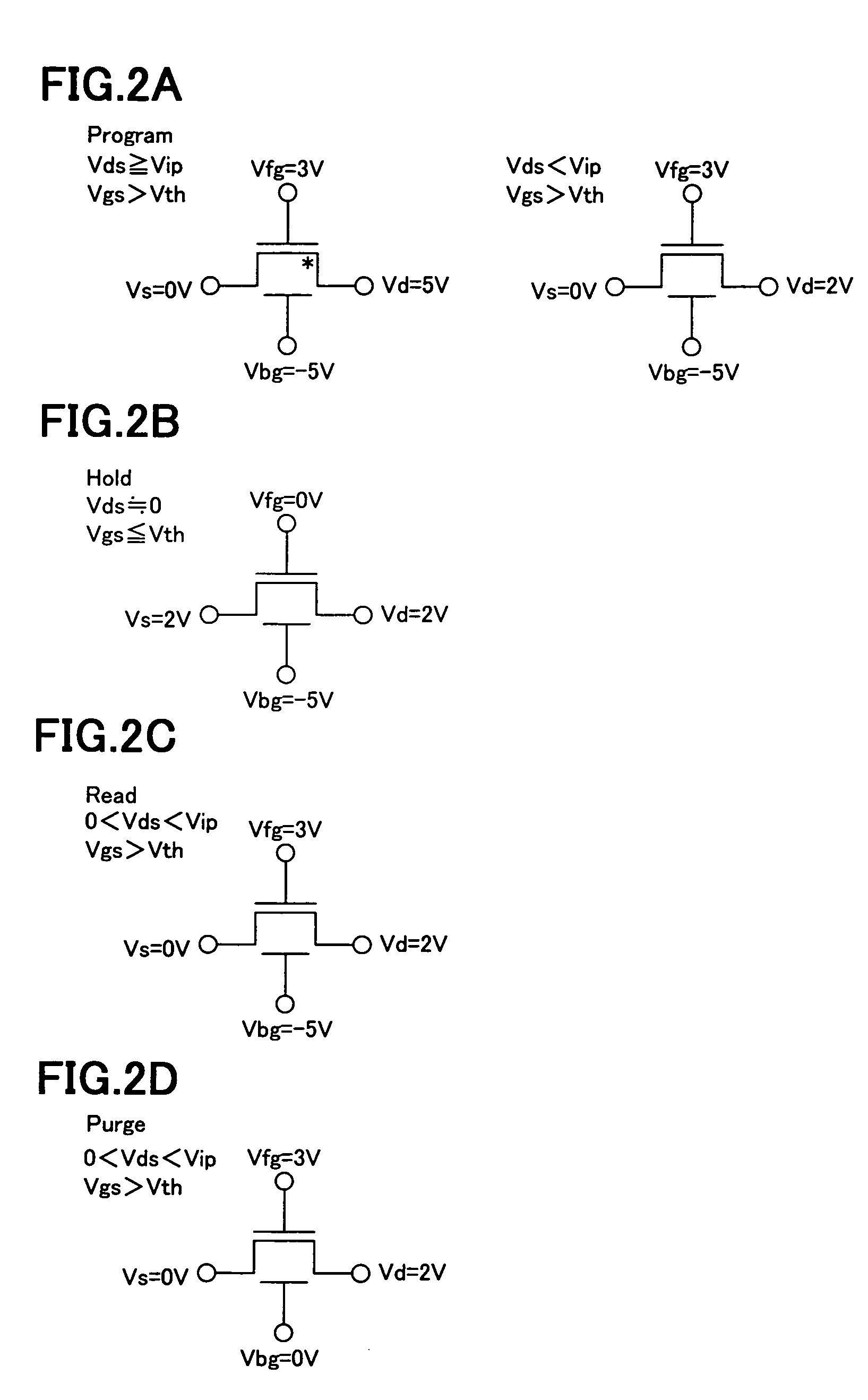
[0154]A DRAM comprising a switching element as well as a TFT which is used as a memory element is described.
[0155]An example of a circuit diagram of a cell array of a DRAM according to the present embodiment is shown in FIG. 8A. The cell array shown in FIG. 8A comprises four memory cells (Cell1, Cell2, Cell3, and Cell4), and each memory cell is provided with a TFT 800 which functions as a memory element and a TFT 801 which functions as a switching element. Although four memory cells are disposed in the memory cell array in FIG. 8A, the number of memory cells is, needless to mention, not limited to this.
[0156]The TFT 800 in each memory cell receives potentials Vbg and Vfg from word lines WLb and WLf respectively, and a potential Vs from a source line SL. The supply of a potential Vd from a bit line BL is controlled by the TFT 801. Switching of the TFT 801 is controlled by a potential supplied to its gate electrode from a select line SeL. Note that, the layout of each wiring is not li...
embodiment 2
[0164]Described in this embodiment is a structure of a memory cell of a DRAM which is mounted on the integrated circuit of the invention.
[0165]FIG. 9A shows a top plan view of memory cell of the present embodiment. A memory cell shown in FIG. 9A comprises a TFT 901 which functions as a memory element. Reference numeral 902 denotes a bit line BL, 903 denotes a source line SL, and 904 denotes a word line WLf. As shown in FIG. 9A, the source line SL 903 is obtained by patterning the same conductive layer as a word line WLb 906.
[0166]FIG. 9B shows a top plan view of the memory cell shown in FIG. 9A, prior to the formation of the bit line BL 902 on a top layer. Reference numeral 905 denotes an active layer of the TFT 902. The word line WLf 904 partially overlaps with the active layer 905 with a second insulating layer (not shown) interposed therebetween, and it functions as a second electrode. In this embodiment, the word line WLf 904 is disposed between the active layer 905 and the bit ...
embodiment 3
[0170]In this embodiment, a configuration of a microprocessor which is one of the integrated circuits of the invention is described.
[0171]FIG. 10 shows a perspective view of a microprocessor of the present embodiment. The microprocessor comprises a substrate 400 which is mounted with a CPU 401, a main memory 403, a clock controller 404, a cache controller 405, a serial interface 406, an I / O port 407, a terminal 408, an interface 409, a cache memory 410, and the like. It is needless to mention that the schematic view of the microprocessor shown in FIG. 10 is only an example and therefore microprocessors in practice take various configurations according to their practical use.
[0172]In order to operate the CPU 401 at a higher rate, a memory which is operable at a corresponding rate to that of the CPU is required. However, when using a high capacity memory which is operable at a high rate and having an access time corresponding to an operating rate of the CPU 401, cost increases general...
PUM
 Abstract
Description
Claims
Application Information
 - R&D
- Intellectual Property
- Life Sciences
- Materials
- Tech Scout
- Unparalleled Data Quality
- Higher Quality Content
- 60% Fewer Hallucinations
Browse by: Latest US Patents, China's latest patents, Technical Efficacy Thesaurus, Application Domain, Technology Topic, Popular Technical Reports.
© 2025 PatSnap. All rights reserved.Legal|Privacy policy|Modern Slavery Act Transparency Statement|Sitemap|About US| Contact US: help@patsnap.com


