Viscoelastic polisher and polishing method using the same

a technology of viscoelastic polisher and polishing method, which is applied in the direction of gear teeth, manufacturing tools, manufacturing apparatus, etc., can solve the problems of reducing the polishing performance, reducing the cost of the formation of grooves, and difficulty in providing the abrasive agent to a portion of the workpiece to be actually polished, so as to achieve the effect of reducing the cost of running

Inactive Publication Date: 2009-05-05
PANASONIC CORP
View PDF22 Cites 5 Cited by
  • Summary
  • Abstract
  • Description
  • Claims
  • Application Information

AI Technical Summary

Benefits of technology

[0021]With these arrangements of the viscoelastic polisher, the viscoelastic polisher can be configured so as to effectively supply an abrasive agent to a portion of a workpiece to be polished at lower costs without processing the surface of the viscoelastic layer provided on the base disk for formation of the grooves. That is, there is no need to provide the grooves in the viscoelastic layer, so that the viscoelastic layer maintains a higher viscosity and a higher elasticity, thereby ensuring enhanced polishing performance. Further, the dynamic pressure acting on the to-be-polished workpiece during polishing is reduced, so that the parallelism of the to-be-polished workpiece with respect to the viscoelastic polisher can be properly maintained. Therefore, the flatness of the polished surface can be improved. Thus, excellent polishing performance can be ensured.
[0037]In this polishing method, partial wear of the viscoelastic layer which may occur when the to-be-polished workpiece is always offset from the viscoelastic layer can be prevented, because the width of the trace of the rotation radius of the to-be-polished workpiece is greater than the radial width of the viscoelastic layer. Therefore, the polisher can be used for a long period of time, so that running costs can be reduced.

Problems solved by technology

In the polishing method in which the polishing operation is thus performed by pressing the to-be-polished workpiece against the viscoelastic polisher 51, the surface of the to-be-polished workpiece is kept in contact with the surface of the viscoelastic polisher, making it difficult to supply the abrasive agent to a portion of the workpiece to be actually polished.
Meanwhile, the conventional polishing method described above has the following drawbacks:1) Reduction in polishing performance due to reduction of surface viscoelasticity associated with processing of the viscoelastic layer for formation of the grooves;2) Increase in costs required for the processing for the formation of the grooves; and3) Change in groove configuration due to wear with time.
However, it is difficult to form the grooves 53 in a soft material.
As a result, the surface of the workpiece being polished is scratched, or the roughness of the finished surface is deteriorated.
The processing for the formation of the grooves 53 increases the costs.

Method used


Image

  • Viscoelastic polisher and polishing method using the same
  • Viscoelastic polisher and polishing method using the same
  • Viscoelastic polisher and polishing method using the same

Examples


first embodiment

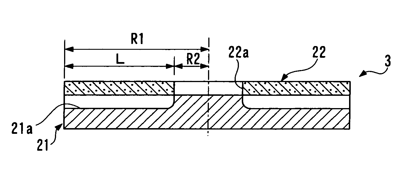
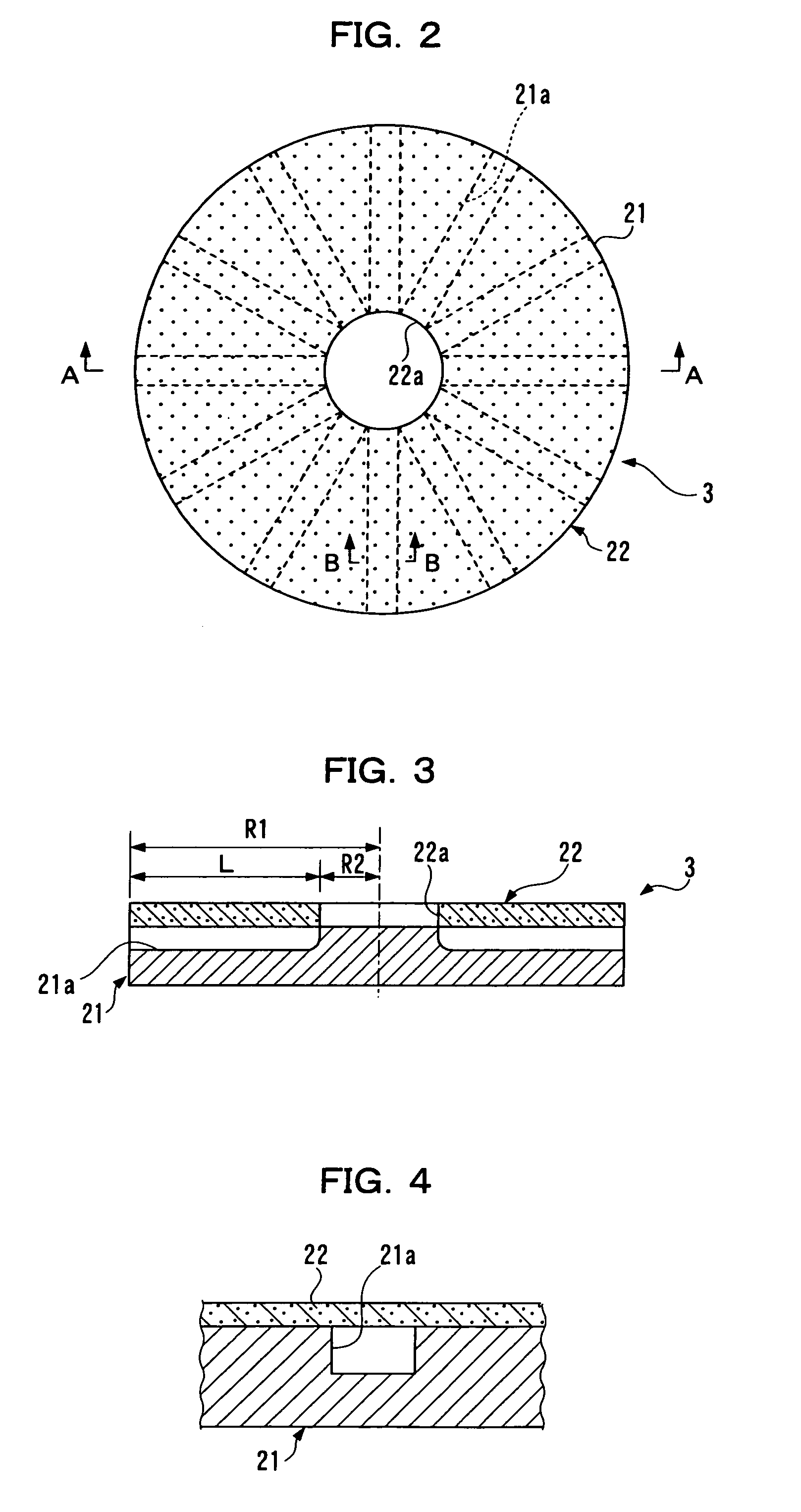
[0055]The viscoelastic polisher according to the present invention and the polishing apparatus for polishing a workpiece with the use of the viscoelastic polisher will be described based on FIGS. 1 to 7.

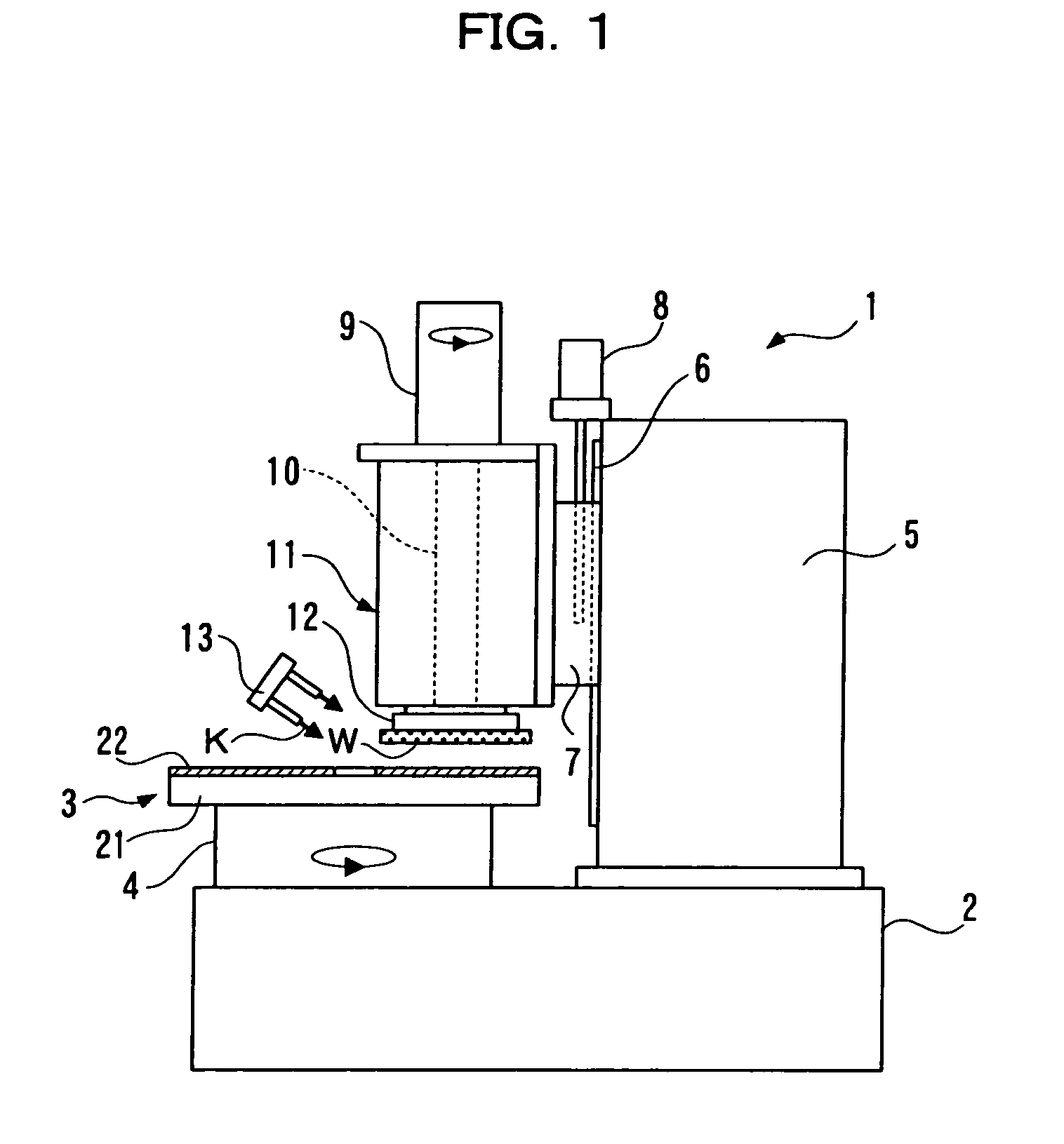
[0056]First, the polishing apparatus will be explained based on FIG. 1.

[0057]The polishing apparatus 1 includes a spin base 4 provided on a bed 2 for rotating a viscoelastic polisher 3 within a horizontal plane, a support column 5 provided upright beside the spin base 4 on the bed 2, a slide member 7 attached to the support column 5 in a vertically movable manner via a vertical guide rail 6, a vertical movement motor 8 provided on an upper side of the support column 5 for vertically moving the slide member 7, for example, via a screw mechanism, a spin head 11 attached to the slide member 7 and having a rotation shaft (also referred to as “spindle”) 10 to be rotated about a vertical axis by a rotation motor 9, and a chuck 12 provided at a lower end of the rotation shaft 10 of the spin...

second embodiment

[0087]Next, a viscoelastic polisher according to the present invention will be described based on FIGS. 8 to 10.

[0088]The viscoelastic polisher according to the second embodiment includes a plurality of annular grooves concentrically provided in addition to radial grooves as provided in the viscoelastic polisher according to the first embodiment described above. In the second embodiment, only a difference from the first embodiment will be mainly described. The same components as those in the first embodiment are denoted by the same numerals, and no explanation will be given thereto.

[0089]As shown in FIGS. 8 to 10, the metal base disk 21 has a plurality of annular grooves (e.g., two annular grooves) 21b having different radii and concentrically provided in the major surface (predetermined surface) thereof in addition to the radial grooves 21a. The annular grooves 21b each have the same depth as the radial grooves 21a, and have a width slightly smaller than that of the radial grooves ...

third embodiment

[0091]Next, a viscoelastic polisher will be described based on FIGS. 11 to 13.

[0092]In the viscoelastic polisher according to the third embodiment, radial grooves provided in the viscoelastic polisher as in the first embodiment described above are each inclined with respect to the radius (center line) of the polisher. In the third embodiment, only a difference from the first embodiment will be mainly described. The same components as those in the first embodiment are denoted by the same numerals, and no explanation will be given thereto.

[0093]As shown in FIGS. 11 to 13, a plurality of radial grooves 21a′ are equiangularly provided in the major surface (predetermined surface) of the metal base disk 21 as intersecting a center line CL passing through the center O of the metal base disk 21 at an angle θ of not greater than ±15 degrees. That is, the grooves are each inclined at the predetermined angle θ with respect to the radius or the center line CL.

[0094]In this case, the same effec...


PUM

PropertyMeasurementUnit
angleaaaaaaaaaa
angleaaaaaaaaaa
viscoelasticaaaaaaaaaa

Abstract

A viscoelastic polisher to be used for polishing. The viscoelastic polisher includes a viscoelastic layer provided on a major surface of a base disk and having a hole of a predetermined radius formed in a center portion thereof, and the base disk has a plurality of grooves equiangularly provided in the major surface thereof as extending radially outward from a center portion thereof. This arrangement ensures stable supply of an abrasive liquid, and obviates a need for formation of grooves in the viscoelastic layer.

Description

CLAIM OF PRIORITY[0001]This applications claims priority under 35 USC 371 to International Application No. PCT / JP2004 / 010176, filed on Jul. 9, 2004, which claims priority to Japanese Patent Application No. 2003-272632, filed on Jul. 10, 2003, the entire contents of which are hereby incorporated by reference.TECHNICAL FIELD[0002]The present invention relates to a viscoelastic polisher and a polishing method using the same.BACKGROUND ART[0003]A conventional viscoelastic polisher and a conventional polishing method using the polisher will briefly be described based on FIGS. 14 and 15. FIG. 14 is a plan view of the viscoelastic polisher, and FIG. 15 is a sectional view of the polisher.[0004]In FIGS. 14 and 15, the viscoelastic polisher indicated by 51 includes a viscoelastic layer 52 provided on a surface of a metal base disk 54. The viscoelastic layer 52 has a plurality of annular grooves 53 concentrically formed therein.[0005]A polishing operation is performed by rotating a workpiece ...

Claims


Application Information

Patent Timeline
Patent Type & Authority Patents(United States)
IPC IPC(8): B24B1/00B24D11/00B24B37/20B24B37/24B24D13/14
CPCB24B37/16
Inventor NISHIHARA, KAZUNARIKURIYAGAWA, TSUNEMOTO
Owner PANASONIC CORP
Why Eureka
Try Eureka