Semiconductor device and a manufacturing method of the same
a manufacturing method and semiconductor technology, applied in the direction of semiconductor/solid-state device details, manufacturing tools, solid-state devices, etc., can solve the problems of affecting the overall thickness reduction of the multi-stage laminated constitution of the semiconductor chip, the thickness of the film-like adhesion member is difficult to achieve below 10 m, and the overall thickness of the semiconductor chip is difficult to redu
- Summary
- Abstract
- Description
- Claims
- Application Information
AI Technical Summary
Benefits of technology
Problems solved by technology
Method used
Image
Examples
embodiment 1
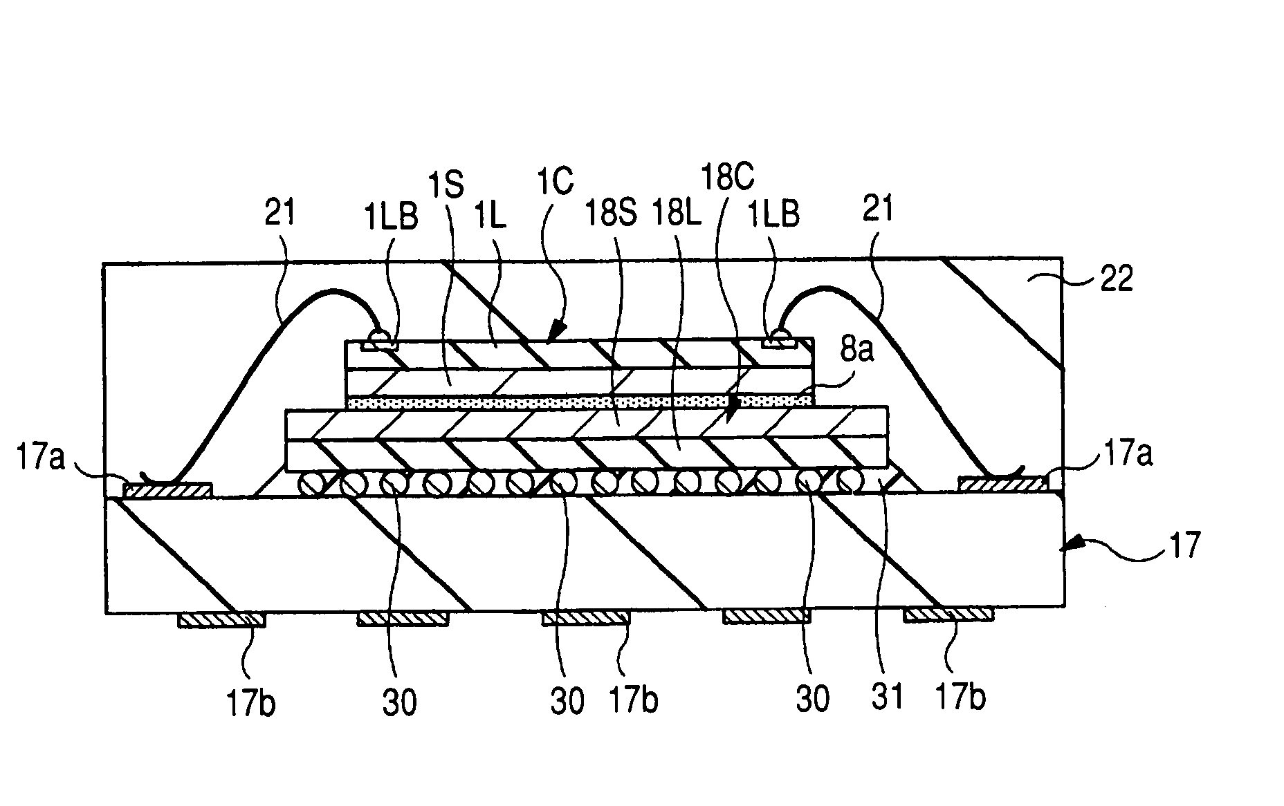
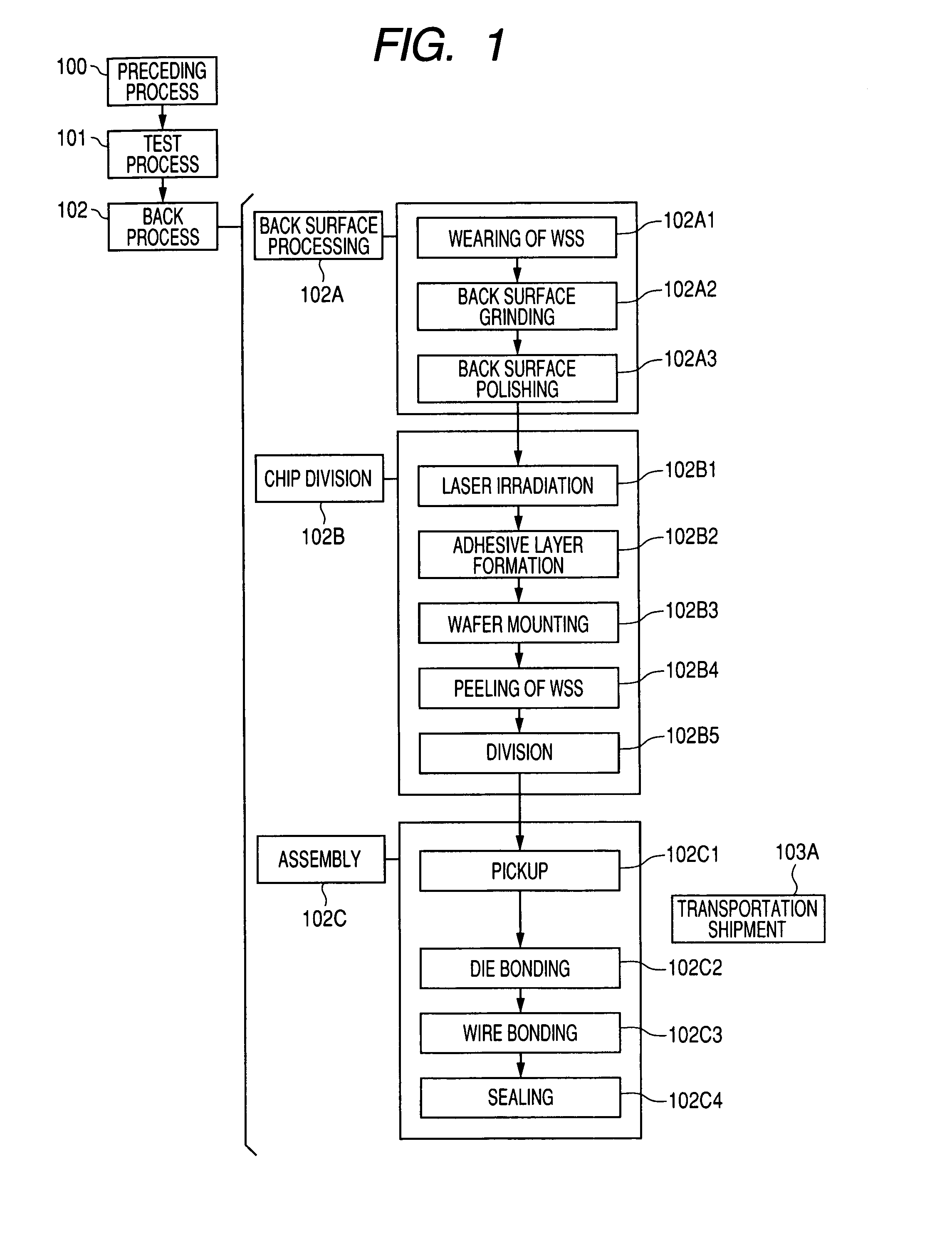
[0074]The manufacturing method of the semiconductor device of Embodiment 1 is explained along the flow diagram of FIG. 1.
[0075]First, in preceding process 100, the semiconductor wafer (henceforth a wafer) which has a main surface and a back surface which serve as the opposite side mutually along a thickness direction is prepared, and a plurality of semiconductor chips (henceforth a chip) are formed in the main surface (device formation surface) of the wafer. This preceding process 100 is also called a wafer process or a wafer fabrication, forms a chip (an element and a circuit) in the main surface of a wafer, and is a step until it changes into the state where an electrical test can be done with a probe etc. There are a film formation step, an impurity introduction (diffusion or ion implantation) step, photolithography step, an etching step, a metallizing step, a cleaning step, a test step between each step, etc. in a preceding process.
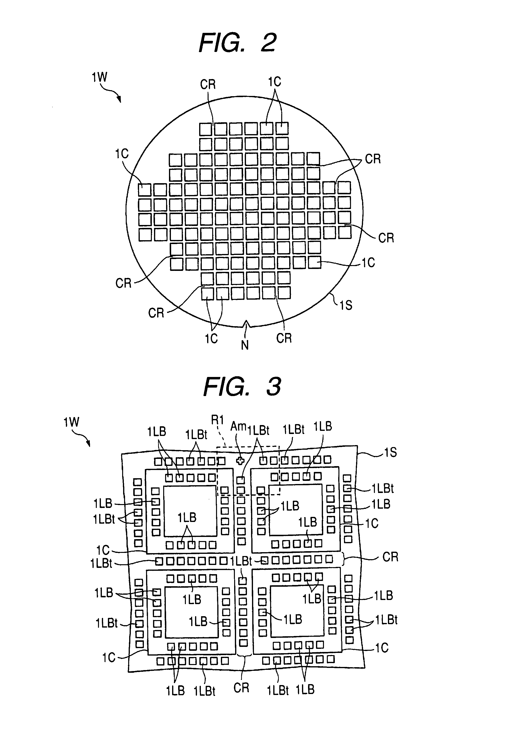
[0076]FIG. 2 shows the whole main surface plan ...
embodiment 2
[0124]In Embodiment 2, like the Embodiment 1, after passing through laser irradiation step 102B1 from preceding process 100 of FIG. 1, in adhesive layer forming step 102B2 of chip division step 102B, an adhesive layer is formed on the back surface of a wafer by the printing method.
[0125]FIG. 26 shows the cross-sectional view of wafer 1W at the time of the above-mentioned adhesive layer forming step 102B2, and FIG. 27 shows the plan view of mask 25A used at the time of the above-mentioned adhesive layer forming step 102B2. Although FIG. 27 was a plan view, in order to make a drawing legible, hatching was given to mask 25A.
[0126]First, on the back surface of wafer 1W, as shown in FIG. 26, after putting mask 25A where alignment is made, squeegee 26 extends binding material 8 of liquid state (paste state) along the back surface of wafer 1W from on this mask 25A. In mask 25A, as shown in FIG. 26 and FIG. 27, opening 25A1 of the almost same plane size as each chip 1C is formed in the corr...
embodiment 3
[0136]The Embodiment 1 and 2 explained the case where an adhesive layer was formed on the back surface of wafer 1W, after the laser irradiation step for forming reforming area LB in the chip division step. Embodiment 3 explains the case where the laser irradiation step for forming reforming area LB is performed in a chip division step after forming an adhesive layer on the back surface of wafer 1W.
[0137]FIG. 36 shows the flow diagram of the semiconductor device of Embodiment 3. In Embodiment 3, like the Embodiment 1, after passing through preceding process 200 and test process 201 of FIG. 36, wearing step of WSS 202A1, back surface grinding step 202A2, and back surface polishing step 202A3 of back surface processing step 202A of back process 202 are performed in order.
[0138]Then, in Embodiment 3, in chip division step 202B, before performing the laser irradiation step for forming reforming area PL, adhesive layer forming step 202B1 is performed. FIG. 37-FIG. 39 show appearance of wa...
PUM
| Property | Measurement | Unit |
|---|---|---|
| diameter | aaaaa | aaaaa |
| length | aaaaa | aaaaa |
| speed | aaaaa | aaaaa |
Abstract
Description
Claims
Application Information
 - R&D
- Intellectual Property
- Life Sciences
- Materials
- Tech Scout
- Unparalleled Data Quality
- Higher Quality Content
- 60% Fewer Hallucinations
Browse by: Latest US Patents, China's latest patents, Technical Efficacy Thesaurus, Application Domain, Technology Topic, Popular Technical Reports.
© 2025 PatSnap. All rights reserved.Legal|Privacy policy|Modern Slavery Act Transparency Statement|Sitemap|About US| Contact US: help@patsnap.com


