Signal transmission apparatus and interconnection structure

Active Publication Date: 2008-11-04
PANASONIC CORP +11
View PDF17 Cites 200 Cited by
  • Summary
  • Abstract
  • Description
  • Claims
  • Application Information

AI Technical Summary

Benefits of technology

[0016]Implementation of the third feature of the invention enables a digital signal with a clock frequency several times higher than ten gigahertz to be transmitted over a transmission line ten millimeters (10 mm) long, and gives bus systems adequate capability to adapt to fut

Problems solved by technology

The long resistance-capacitance (RC) delays associated with these buses become intolerable in a chip having a gigahertz clock, so chips operating at gigahertz speeds conventionally have many repeater circuits.
These repeater circuits, however, together with RC circuit elements, consume enough energy to generate fluctuations refe

Method used


Image

  • Signal transmission apparatus and interconnection structure
  • Signal transmission apparatus and interconnection structure
  • Signal transmission apparatus and interconnection structure

Examples


third embodiment

[0094]The third embodiment, having the double-coupler configuration with a terminating resistor shown in FIG. 3, operates the receiver 4 by signal transition energy alone. The terminating resistor 6a connected across the output end of the energy output line pair of the directional coupler 5c avoids energy collisions by allowing a brief discharge to take place when the logic level of the signal inverts (following the transition, the signal energy is converted uniformly to heat).

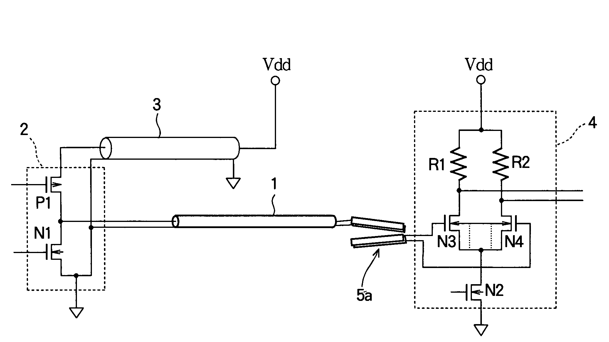
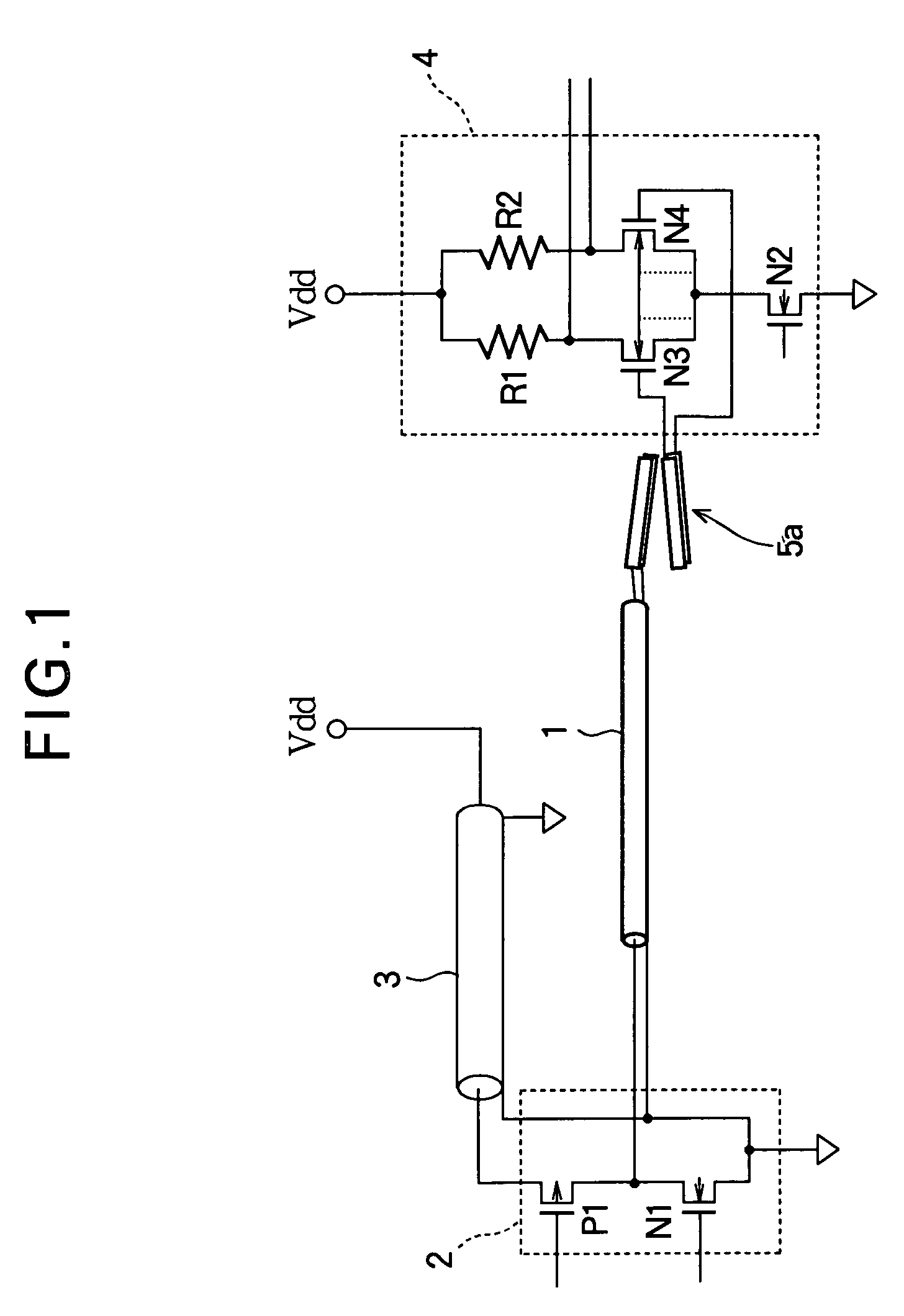
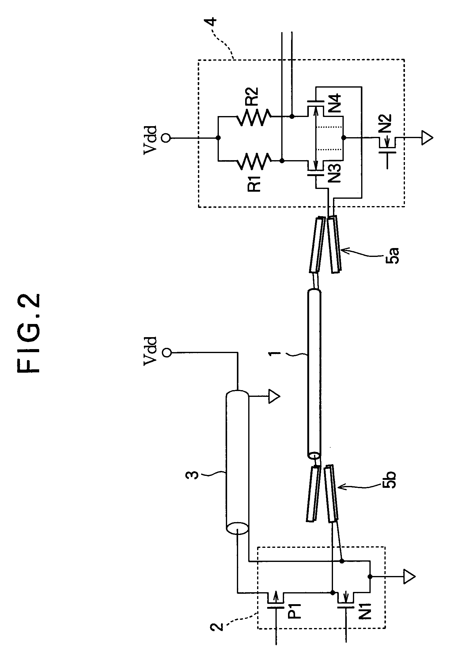
[0095]The fourth embodiment, having a single coupler at the transmitting end as shown in FIG. 4, is a simplified version of the third embodiment, applicable when the signal transmission line 1 approaches light-speed performance. The directional coupler 5b, which is connected to the transmitting end of the signal transmission line 1, is a high pass filter with a smooth passband from, for example, one hundred megahertz to several times ten gigahertz.

[0096]When the signal output from the driver is transmitted on ...

fifth embodiment

[0151]Although NMOS transistors N11 and N12 operate in synchronization with an input differential signal in the fifth embodiment in FIG. 5, there is no need for them to operate complementarily. The different drain voltages of NMOS transistors N11 and N12 cause a difference in their on-resistance, even if their dimensions are the same, but the difference in the on-resistance presents no problem, because the purpose of NMOS transistor N12 is to provide a reference to ground.

[0152]Since the on-resistance of the driver 12 may be fairly high, no further current-limiting measures may be necessary, but if the on-resistance of the transistors in the driver 12 is low, a resistor R10 may be inserted on the power-supply side as shown in FIG. 5.

[0153]Although the sense amplifier in the receiver 14 must be designed to detect small signal swings, this is possible within the realm of ordinary device design. The dimensions of the directional couplers 5b, 5c also enable them to be formed by use of o...

second embodiment

[0187]The embodiments described above may be modified for bi-directional transmission of digital signals by branching the transmitting and receiving ends of the signal transmission line and providing a driver and a receiver at each end. FIG. 26 shows an example of this modification based on the The directional couplers 5a, 5b obviate the need for tri-state drivers. The directional couplers 5b disposed between the drivers 2 and the signal transmission line 1 suffice to assure that when one driver is inactive, it will not interfere with the transmission of a digital signal by the other driver.


PUM


Abstract

Apparatus for transmitting a digital signal within, for example, an integrated circuit includes a signal transmission line with a directional coupler at one or both ends. The directional coupler blocks the direct-current component of the digital signal while transmitting the alternating-current component, including enough higher harmonics to transmit a well-defined pulse waveform. A suitable directional coupler consists of two adjacent line pairs in materials with different dielectric constants. The apparatus may also include a driver of the inverter type, a receiver of the differential amplifier type, a terminating resistor, and a power-ground transmission line pair for supplying power to the driver. An all-metallic transmission-line structure is preferably maintained from the output interconnections in the driver to the input interconnections in the receiver.

Description

BACKGROUND OF THE INVENTION[0001]1. Field of the Invention[0002]The present invention relates to signal transmission apparatus for transmitting a digital (pulse) signal on a transmission line, and in particular to the signal-line structure of the transmission line.[0003]2. Description of the Related Art[0004]A digital signal has a complex waveform that can be analyzed as a Fourier series of sinewave components ranging from a direct-current (dc) component to a fundamental clock frequency component and higher harmonics thereof. Due to the complexity of its waveform, a digital signal cannot be transmitted through a filter circuit such as the inductor-capacitor (LC) filter circuits that are employed when only a single sinewave frequency, or a narrow band of frequencies, is transmitted. Conventional digital signal transmission apparatus uses dc coupling between the transmission line and its driver and receiver. Because of the conventional dc coupling, the dc component of the digital sign...

Claims


Application Information

Patent Timeline
IPC IPC(8): H03K17/16H03K19/094H01P1/00H01P1/22H01P3/02H01P3/08H01P5/18H04L5/14H04L25/02
CPCH04L5/1461A61L2/10H02J7/0044
Inventor OTSUKA, KANJIUSAMI, TAMOTSU
Owner PANASONIC CORP
Why Eureka
Try Eureka