
Method for removal of biofilm

a biofilm and biofilm technology, applied in the field of biofilm removal, can solve the problems of affecting the effect of biofilm removal

Inactive Publication Date: 2008-08-05
ARXADA LLC
View PDF37 Cites 22 Cited by
  • Summary
  • Abstract
  • Description
  • Claims
  • Application Information

AI Technical Summary

Benefits of technology

Chlorinated hydantoins effectively disintegrate and inhibit biofilm growth, outperforming traditional biocides like NaOCl and NaOBr, with MCDMH demonstrating superior biofilm inhibition and photostability, allowing for efficient biofilm control and removal without the need for high concentrations, thus addressing the challenges of biofilm resistance and environmental concerns.

Problems solved by technology

Biofilms create problems for industry from corroding water pipes to computer-chip malfunctions.
Any man-made device immersed in an aquatic habitat is susceptible to colonization by microbial biofilm.
For the industrial manufacturer, biofilm clusters represent a source of microbial inoculation in a system and may cause plugging problems.
In water treatment facilities, the formation of suspended biofilm produces a bulked biological sludge which settles poorly and is difficult to compact in the clarification process.
In addition to their role as fouling agents, biofilms may also have adverse effects on people, including altering their resistance to antibiotics and affecting the immune system.
The dynamic nature of biofilms makes it difficult to measure and monitor biofouling.
Thus, the complexity of biofilms has reduced the effectiveness of treatment and removal strategies.
However, it has been shown that various biocides are less effective against biofilm than dispersed cells of the same organism.
The data indicate that the transport of free chlorine into the biofilm is a major rate-limiting factor, and increasing concentrations did not increase biocidal efficiency.
However, while effective, it is still not an efficient halogen source when applied to biofilm.
However, this method poses environmental issues.
However, high levels of these expensive chemicals are needed because their effectiveness is rapidly reduced as a result of exposure to the various physical and chemical conditions in specific applications since the concentration of the biocides is considerably reduced by the time the biocides reach the biofilm.

Method used


Image

  • Method for removal of biofilm
  • Method for removal of biofilm
  • Method for removal of biofilm

Examples


example 1

Biofilm Inhibition Control Efficacy

[0032]The efficacy of biocides and biocides with dispersants was estimated by a reduction of biofilm dry weight in test flasks, compared to untreated controls. Biofilm development was determined gravimetrically by the methods described in Ludyansky, M., Colby, S., A Laboratory Method for Evaluating Biocidal Efficacy on Biofilms, Cooling Tower Institute, Paper TP96-07 (1996).

[0033]The sheathed Sphaerotilus natans (ATCC 15291), which is known to be very resistant to any chemical control and found in a variety of applications (cooling water systems, paper process waters, and sewage treatment processes), was used in the tests.

[0034]The bacteria were cultivated at 25-30° C. in a 5% CGY medium which contained: 5 g of casitone (Difco), 10 g of glycerol, and 1 g of yeast autolysate (Difco) per liter of DI water. The inocula contained approximately 106 cells per milliliter. 8 oz. flasks were filled with 150 ml of 5% CGY media and 1 ml of Sphaerotilus natans...

example 2

Biofilm Removal Control Efficacy

[0038]Sphaerotilus natans (ATCC 15291), as in Example 1, was used in the tests described below.

Biofilm Test System

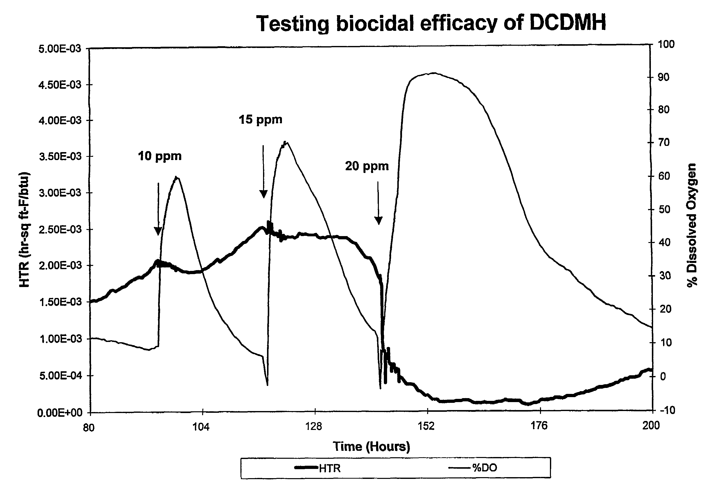
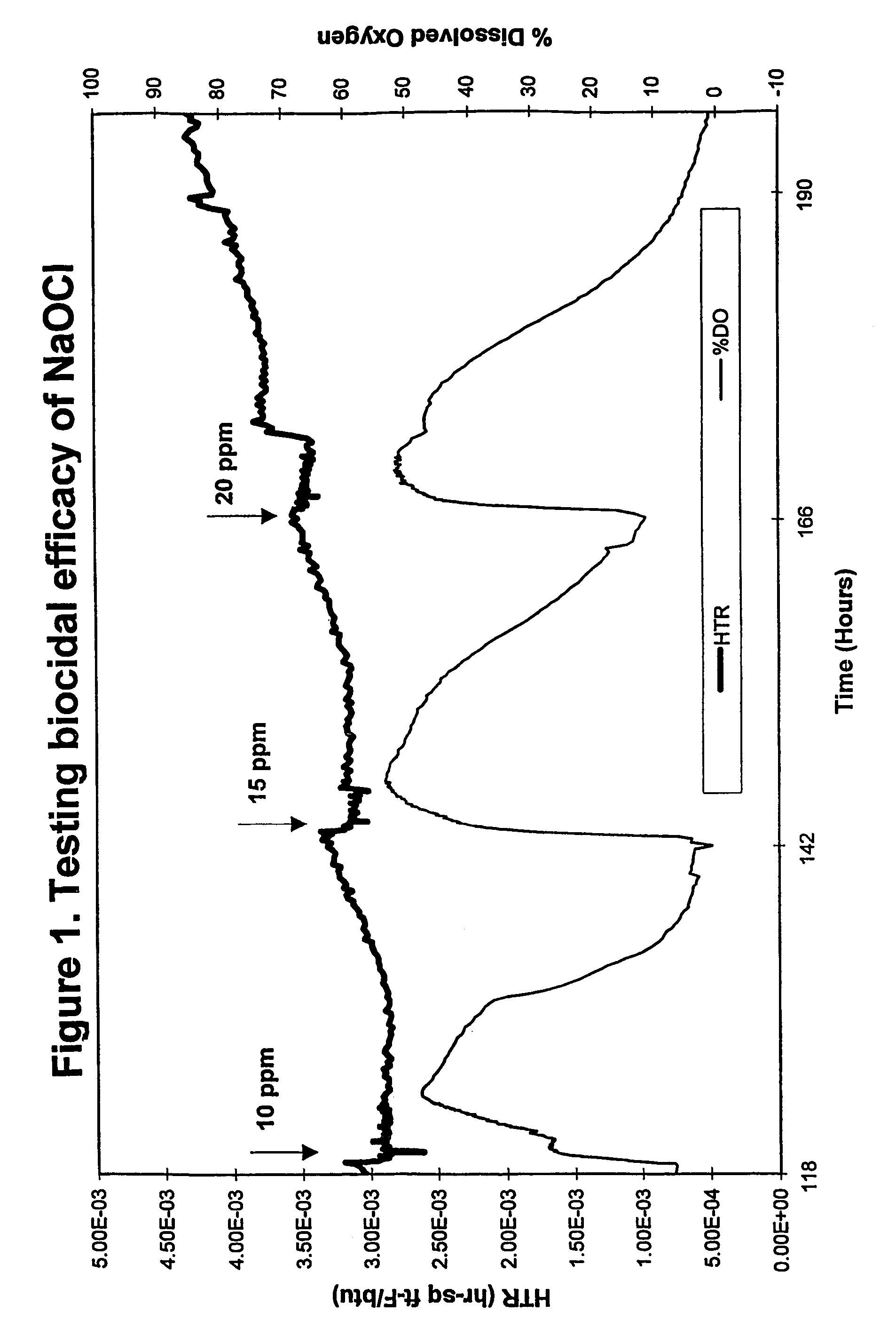
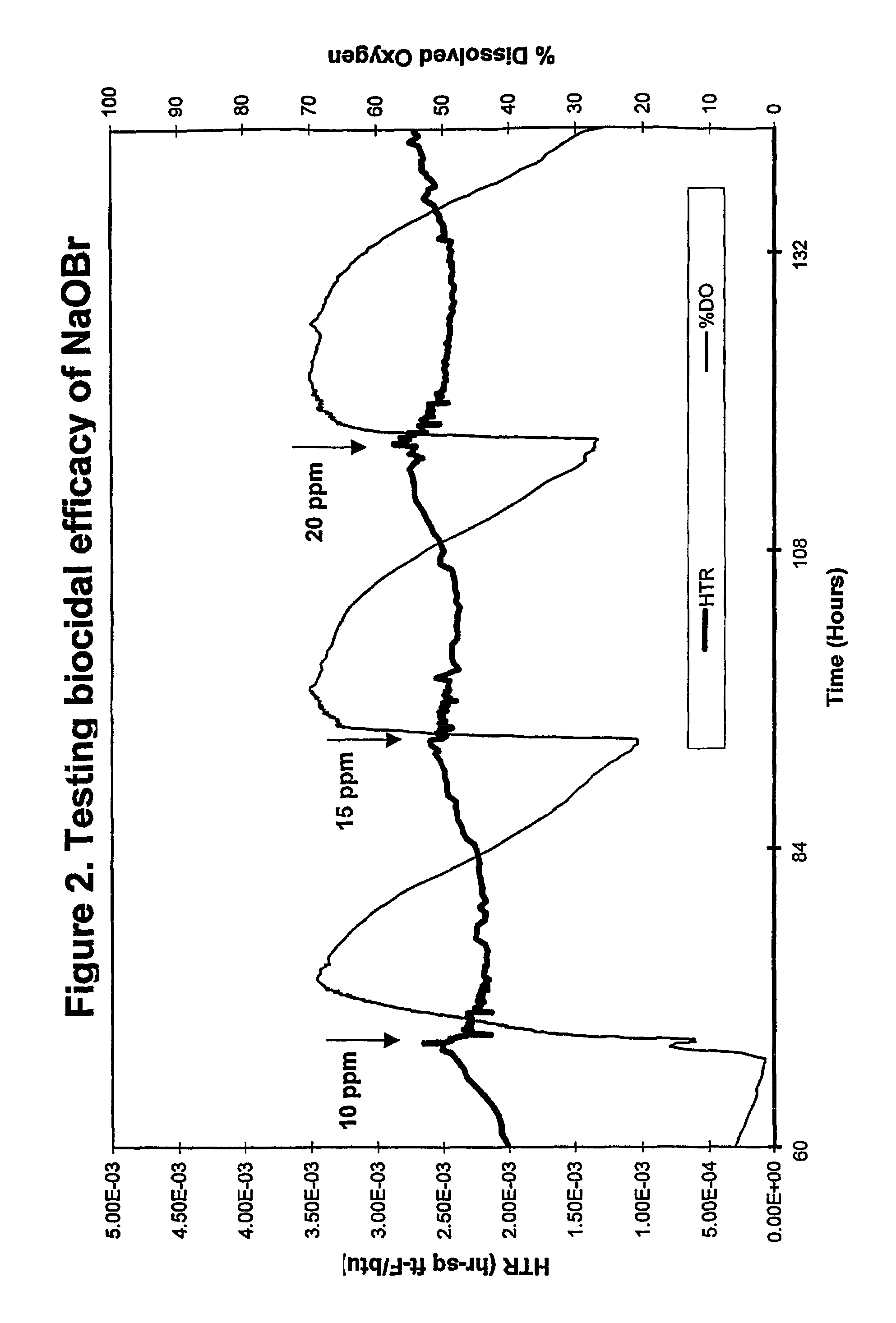
[0039]An on-line testing system for chlorinated biocide efficacy testing was used to provide a real-time, non-destructive method for biofilm monitoring and measurement. The system monitors the heat transfer resistance (HTR) which correlates to biofilm formation and accumulation, and dissolved oxygen (DO) level in the bulk water which correlates with changes in biofilm activity. The system design, parameters and growth conditions are disclosed in Ludensky, M., “An Automated System for Biocide Testing on Biofilms.”Journal of Industrial Microbiology and Biotechnology, 20:109-115 (1998).

[0040]The system consisted of a continuous-flow heat-exchange loop, a biological growth reactor (chemostat) and subsystems for life support, biofilm measurement, and environmental control. All system parameters, including water flow, temperature, dilution rate ...

example 3

[0052]This example demonstrates the enhanced photostability of MCDMH as compared to NaOCl when test solutions thereof are exposed to simulated sunlight.

[0053]Test solutions were prepared by adding to tap water having a temperature of 22° C. and a pH of 7.8 NaOCl and MCDMH at the concentrations indicated in Table 4 below. These solutions were illuminated by UVA-340 fluorescent lights that simulate the spectral radiance of the sun at the surface of the earth. The test samples were covered with quartz plates, transparent to ultraviolet light, to prevent evaporation. Total halogen concentrations were measured as a function of time. The generated active halogen decay curves were analyzed using first order kinetic algorithms and the corresponding active halogen half-lives calculated. The results are shown in Table 4.

[0054]As shown in Table 4, MCDMH provides dramatically superior photostability to NaOCl. The observed active halogen half-life for MCDMH was 108 hours compared to 1.1 hour for...


PUM

PropertyMeasurementUnit
pHaaaaaaaaaa
temperatureaaaaaaaaaa
aqueousaaaaaaaaaa

Abstract

The present invention provides a method for the removal of biofilm, flocculent bulked sludge or bulked biologically active sludge from an aqueous system. The method involves adding one or more chlorinated hydantoins, such as dichloro- or monochlorodialkylhydantoin, to the aqueous system. Alternatively, the chlorinated hydantoin may be formed in situ by adding a chlorine source and an alkylated hydantoin separately to the aqueous system. The invention is particularly advantageous because of the outstanding photostability of the chlorinated hydantoin solutions even when exposed to sunlight.

Description

PRIORITY DATA [0001]This application is a U.S. National Phase application of International Patent Application No. PCT / US2003 / 017882 filed Jun. 6, 2003, which claims priority from U.S. Provisional Application Ser. No. 60 / 435,680 filed Dec. 20, 2002, which is incorporated hereby by reference.BACKGROUND OF THE INVENTION [0002]Biofilm may be defined as an undesirable accumulation of microorganisms on a surface and in flocculent masses. It is estimated that more than 99% of all the planet's bacteria live in biofilm communities. Biofilm consists of cells immobilized in a substratum, frequently embedded in an organic polymer matrix of microbial origin, which can restrict the diffusion of substances and bind antimicrobials. In flowing aquatic environments, a biofilm consists of a sticky and absorptive polysaccharide matrix encompassing microorganisms. Biofilm bacteria are morphologically and metabolically distinct from free-floating bacteria. Their structural organization is a characteristi...

Claims


Application Information

Patent Timeline
Patent Type & Authority Patents(United States)
IPC IPC(8): C02F1/76A01N59/00A61L2/16D21H21/04
CPCA01N59/00A61L2/16C02F1/76C02F2103/023D21H21/04C02F2303/02C02F2303/06C02F2303/12C02F2303/20C02F2103/42Y02W10/37Y02W10/10
Inventor LUDENSKY, MICHAELSWEENY, PHILIP G.
Owner ARXADA LLC
Learn More