
High resistance silicon wafer and its manufacturing method

a technology of high resistance and silicon wafer, which is applied in the direction of basic electric elements, electrical equipment, semiconductor devices, etc., can solve the problems of high cost of compound semiconductor substrates, large amount of power required by cmos, and inability to meet the requirements of rf circuits, etc., and achieves uniform gettering ability, and high thermal anneal efficiency.

Active Publication Date: 2008-07-08
SUMITOMO MITSUBISHI SILICON CORP
View PDF9 Cites 23 Cited by
  • Summary
  • Abstract
  • Description
  • Claims
  • Application Information

AI Technical Summary

Benefits of technology

"The present invention relates to a high-resistance silicon wafer with improved resistivity and reduced strength. The invention focuses on the formation of oxygen precipitates in the wafer and the prevention of thermal donor formation. The invention also addresses the issue of resistivity variation caused by the removal of the COP. The first high-resistance silicon wafer has a high carbon concentration, while the second high-resistance silicon wafer uses a crystal free from the COP. The invention aims to provide a high-resistance silicon wafer with excellent resistivity and reduced strength, as well as a low oxygen concentration to prevent thermal donor formation."

Problems solved by technology

However, the compound semiconductor substrate is very expensive.
Meanwhile, a silicon CMOS requires a large amount of power, so that it has been considered that it is not suitable for the RF circuit.
However, since a quartz crucible is used when a silicon single crystal is manufactured by the CZ method, oxygen is contained in the crystal in an oversaturated state.
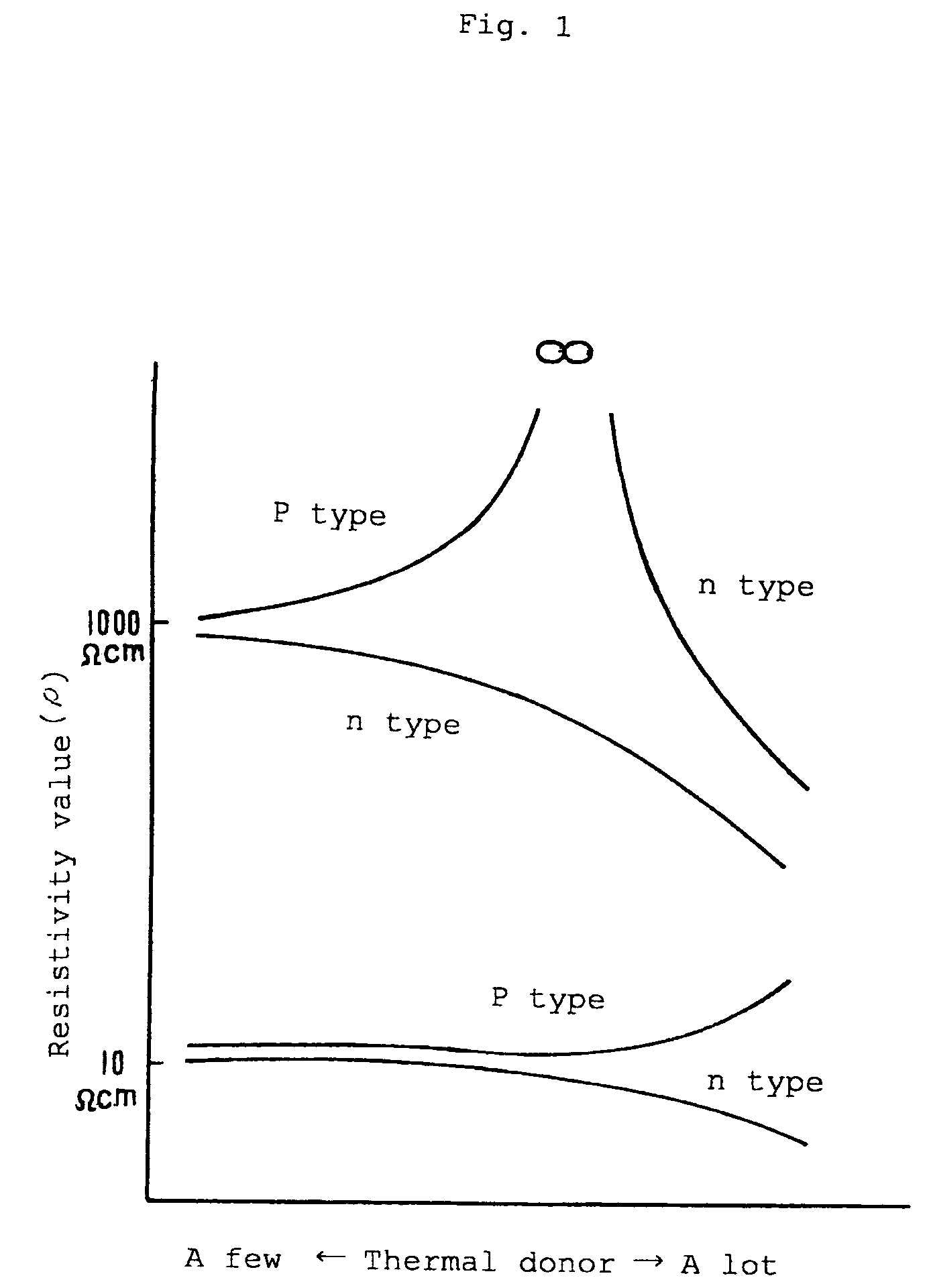
Since a thermal donor is formed by this oxygen in a heat treatment in the process of forming the circuit of the device, there is a big problem such that resistivity of the wafer unstably varies on the side of a device maker.
However, in a case of the high-resistance wafer in which the dopant is limited, when it is an n type, the resistivity is considerably reduced as the thermal donor is increased.
However, the low-oxygen silicon wafer which needs to use the MCZ method or the special crucible is surely expensive as compared with the general-purpose silicon wafer having a relatively high oxygen concentration which is manufactured by the normal CZ method.
In addition, oxygen lowering has a technical limitation.
In addition, in the silicon wafer having a low oxygen concentration, there is a problem of slipping and the like because of the lowering of mechanical strength caused by reduction in oxygen concentration.
According to this technique, the manufacturing cost of the initial wafer becomes low because the general-purpose silicon wafer having high initial oxygen concentration is used.
First, to lower the remaining oxygen concentration in the product silicon wafer causes the mechanical strength of the wafer to be lowered. This is clear from the fact that slip dislocation generated from a wafer supporting part in the heat treatment is fixed by oxygen and as a result, a slip length is lowered as the oxygen concentration is increased [M. Akatsuka et al., Jpn. J. Appl. Phys., 36 (1997) L1422]. Meanwhile, the oxygen precipitate (BMD) is a factor of affecting the strength. The influence of BMD to the strength is complicated. For example, when the heat and stress of one's own weight added to the wafer is not so large, the movement of the slip dislocation is prevented and the strength is improved (patent document 1), but when the heat and the stress of one's own weight is large, the BMD itself becomes a source of the slip dislocation, so that the strength is lowered and the wafer is probably warped (K. Sueoka et al., Jpn. J. Appl. Phys., 36 (1997) 7095). The heat and the stress of one's weight applied to the wafer in the real device process depend on a device structure or a thermal sequence, and it is expected to be increased in some cases.
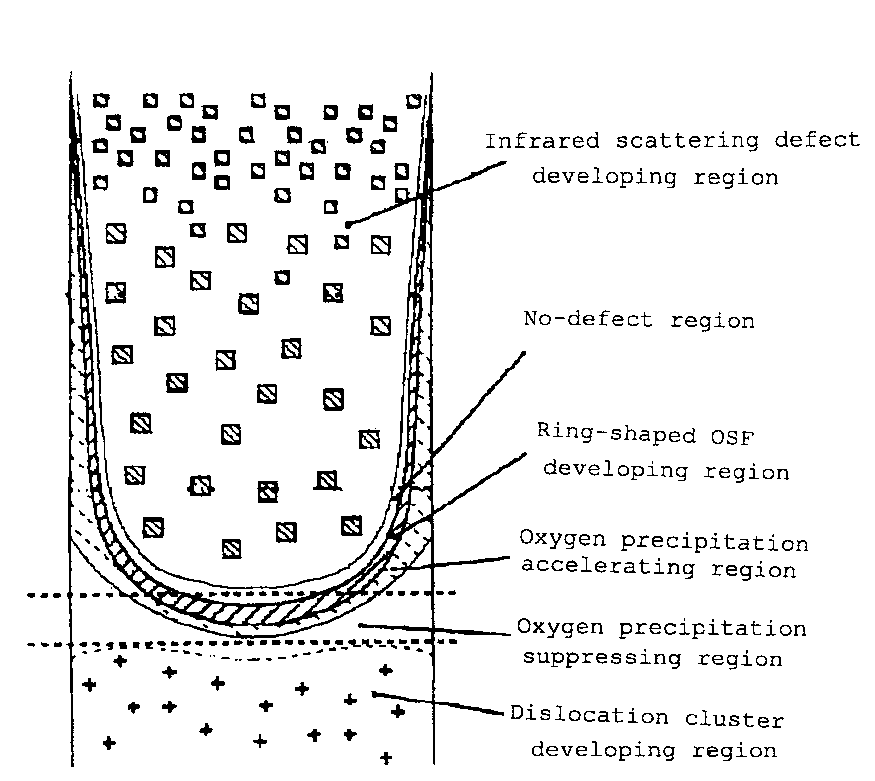
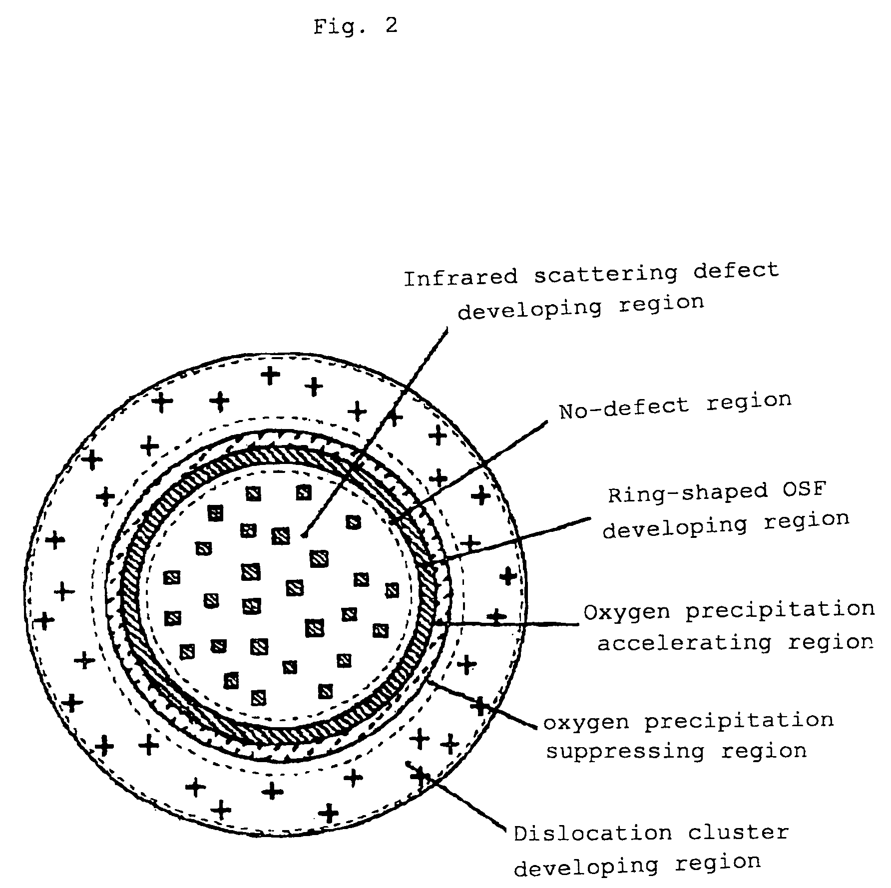
The second problem is resistance variation along with hydrogen annealing or argon annealing for removing COP [Crystal Originated Particle: aggregation of holes and a void defect surrounded by (111) surface].
Therefore, it is difficult to manufacture the crystal having perfectly no defect on the whole region in the diameter direction with high yield.
However, since the argon annealing and the hydrogen annealing are basically technique for performing heat treatments on the wafer at high temperature for a long time in a reducing atmosphere (argon has a reducing property at high temperature), the wafer could be contaminated with heavy metal impurities from a heat treatment furnace.
Therefore, the argon annealing and the hydrogen annealing are not desirable.
As a result, it is difficult to manufacture a high-resistance wafer having a predetermined resistivity range, with high precision.
Thus, when the high-resistance wafer is manufactured, the argon annealing and the hydrogen annealing for eliminating the COP are undesirable technique.

Method used


Image

  • High resistance silicon wafer and its manufacturing method
  • High resistance silicon wafer and its manufacturing method
  • High resistance silicon wafer and its manufacturing method

Examples


first embodiment

[0050]According to this embodiment, a high-oxygen, high-resistance and carbon-doped silicon single crystal is formed by a normal CZ method and a primary substrate is formed from the silicon single crystal such that an OSF ring exists at a periphery, a COP exists inside, an oxygen concentration is 12×1017 atoms / cm3 (ASTM F-121, 1979) or more, a carbon concentration is 0.5×10¹⁶ atoms / cm3 or more, and resistance is as high as 100 Ω or more at steps S1 to S3.

[0051]If needed, an oxygen outward diffusion heat treatment is performed on the primary substrate at 1100 to 1250° C. for 1 to 5 hours at step S4. By this oxygen outward diffusion heat treatment, an oxygen precipitate (BMD) is prevented from being generated in the heat treatment to be described below. Thus, a DZ (Denuded Zone) layer is formed at least 5 μm in depth from a surface of a product wafer.

[0052]The oxygen outward diffusion heat treatment can be performed in an atmosphere of mixed gas of nitrogen gas and oxygen gas as descr...

second embodiment

[0058]According to this embodiment, a crystal free from the COP shown by A-B in FIG. 3 is grown lengthwise in the pulling axis direction by a CZ pulling apparatus in which a hot zone and the like is devised, and a silicon wafer having no defect on the whole surface is provided from the crystal part at steps S1 and S2. More specifically, the wafer having no defect in which a density of the grown-in defect is 1×103 cm−3 or less, which is detected by seco etching. This primary substrate has high oxygen [an oxygen concentration is 14×1017 atoms / cm3 (ASTM F-121, 1979) or more] and high resistance (100 Ωm or more).

[0059]In order to improve the mechanical strength, carbon doping (0.5×10¹⁶ atoms / cm3 or more) can be performed at step S3. In this case, since growth of the oxygen precipitate (BMD) on the wafer surface layer is promoted in the subsequent heat treatment, the oxygen concentration in the primary substrate is allowed to be 12×1017 atoms / cm3 (ASTM F-121, 1979) or more.

[0060]If requi...

working example 1

[0105]There were prepared a plurality of 8-inch p-type of sample wafers which were cut out from a normally formed silicon single crystal ingot and on which an oxygen donor eliminating heat treatment was performed at 650° C. for 30 minutes so as to have resistivity of about 750 Ωcm, an oxygen concentration (ASTM F-121, 1979) of about 11×1017 atoms / cm3 and a carbon concentration of about 1×10¹⁶ atoms / cm3. Then, a heat treatment for forming an oxygen precipitate nucleus and a heat treatment for growing the oxygen precipitate were performed like in the comparative example 3 so that a remaining oxygen concentration (ASTM F-121, 1979) might be about 4.5×10¹⁷ atoms / cm3.

[0106]When a density of oxygen precipitate (BMD) having a size of 0.2 μm or more existing in the wafer was measured, it was 4.3 to 6.2×10⁶ / cm2 which was about the same as that in the comparative example 4, in which the remaining oxygen concentration (ASTM F-121, 1979) was lowered from the initial oxygen concentration (ASTM F...


PUM

PropertyMeasurementUnit
sizeaaaaaaaaaa
resistivityaaaaaaaaaa
sizeaaaaaaaaaa

Abstract

A high-resistance silicon wafer is manufactured in which a gettering ability, mechanical strength, and economical efficiency are excellent and an oxygen thermal donor is effectively prevented from being generated in a heat treatment for forming a circuit, which is implemented on the side of a device maker. A heat treatment for forming an oxygen precipitate nucleus is performed at 500 to 900° C. for 5 hours or more in a non-oxidizing atmosphere and a heat treatment for growing an oxygen precipitate is performed at 950 to 1050° C. for 10 hours or more on a high-oxygen and carbon-doped high-resistance silicon wafer in which resistivity is 100 Ωcm or more, an oxygen concentration is 14×1017 atoms / cm3 (ASTM F-121, 1979) or more and a carbon concentration is 0.5×10¹⁶ atoms / cm3 or more. By these heat treatments, a remaining oxygen concentration in the wafer is controlled to be 12×1017 atoms / cm3 (ASTM F-121, 1979) or less. Thus, there is provided a high-resistance, low-oxygen and high-strength silicon wafer in which resistivity is 100 Ωcm or more and an oxygen precipitate (BMD) having a size of 0.2 μm is formed so as to have high density of 1×10⁴ / cm2 or more.

Description

TECHNICAL FIELD[0001]The present invention relates to a high-resistance silicon wafer used in a support substrate and the like in a high-frequency communication device and its manufacturing method.BACKGROUND ART[0002]Recently, a demand for high-resistance substrate is increased along with the widespread use of a high-frequency communication device used in a short-distance wireless LAN. Conventionally, a compound semiconductor such as GaAs has been mainly used for a support substrate of a RF (Radio Frequency high frequency) which requires high resistance. However, the compound semiconductor substrate is very expensive.[0003]Meanwhile, a silicon CMOS requires a large amount of power, so that it has been considered that it is not suitable for the RF circuit. However, because of recent considerable miniaturization and development of designing, it can be applied to the RD circuit. Therefore, a high-resistance silicon wafer which is excellent in RF characteristics and excellent in economi...

Claims


Application Information

Patent Timeline
Patent Type & Authority Patents(United States)
IPC IPC(8): H01L29/36H01L21/322H01L21/26
CPCH01L21/3225H01L21/26H01L21/322
Inventor TAKASE, NOBUMITSUNISHIKAWA, HIDESHIITO, MAKOTOSUEOKA, KOJISADAMITSU, SHINSUKE
Owner SUMITOMO MITSUBISHI SILICON CORP
Learn More