
Dual-bearing reel

a reel and dual-bearing technology, applied in the field of dual-bearing reels, can solve the problems of metal support members corroding, increasing the surface roughness of the support member, and affecting the strength and shape of the metal support members

Active Publication Date: 2020-02-25
SHIMANO COMPONENTS MALAYSIA
View PDF7 Cites 0 Cited by
  • Summary
  • Abstract
  • Description
  • Claims
  • Application Information

AI Technical Summary

Benefits of technology

In the present dual-bearing reel, the support part is made of resin, and therefore it is possible to prevent corrosion of the support part. That is, in the present dual-bearing reel, deformation of the support part and reduction in the strength of the support part due to corrosion do not occur; hence, the clutch yoke can be suitably guided by the support part. In addition, it is possible to prevent the support part and the clutch yoke from becoming stuck by deposits and suppress an increase in the surface roughness of the support part, and therefore the clutch yoke can be suitably guided by the support part.
Further, in the present dual-bearing reel, corrosion of the main body part can be prevented since the main body part is made of resin. With this configuration, there is no occurrence of a change in the posture of the support part due to corrosion of the main body part, whereby the clutch yoke can be more suitably guided by the support part.
With this configuration, the reinforcing member is disposed on the inner peripheral portion of the guide shaft, whereby the strength of the guide shaft can be improved. Therefore, the clutch yoke can be suitably guided by the support part (guide shaft).
In the dual-bearing reel according to yet another aspect of the present disclosure, the reinforcing member is preferably made of metal. With this configuration, the strength of the protruding portion can be further improved, and the clutch yoke can be suitably guided by the support part (protruding portion).
According to the present invention, it is possible to suitably guide the clutch yoke in the dual-bearing reel.

Problems solved by technology

In a conventional dual-bearing reel, a support member made of metal might corrode when water, salt water or the like adheres thereto.
Here, when there is corrosion of the metal support member, the strength and shape of the metal support member are impaired.
In addition, the support member and the clutch yoke are stuck due to the salt deposited thereto, or the surface roughness of the support member increases.
In other words, with the conventional support member, there is a possibility that the clutch yoke cannot be suitably guided in the axial direction.

Method used


Image

  • Dual-bearing reel
  • Dual-bearing reel
  • Dual-bearing reel

Examples


Embodiment Construction

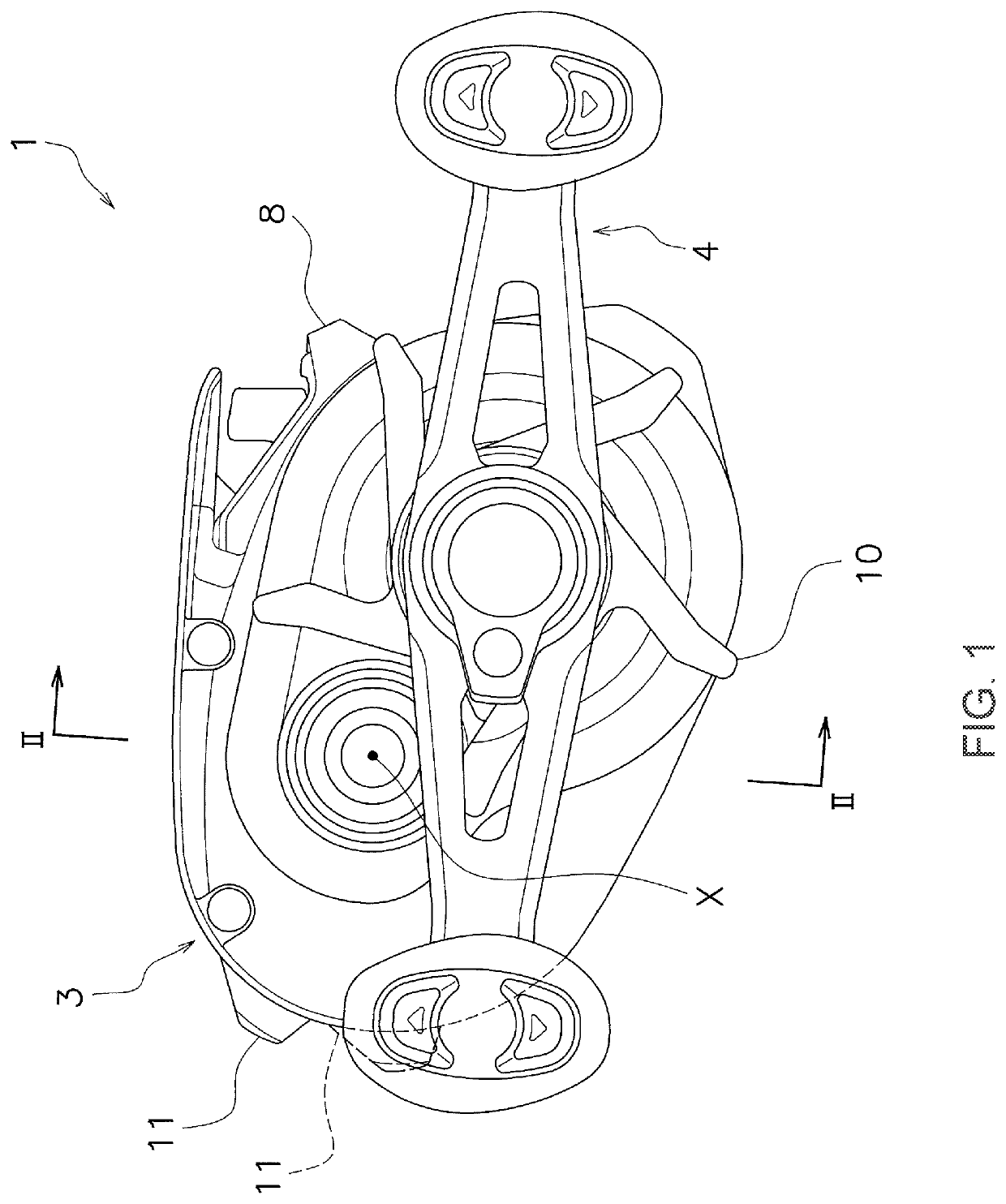
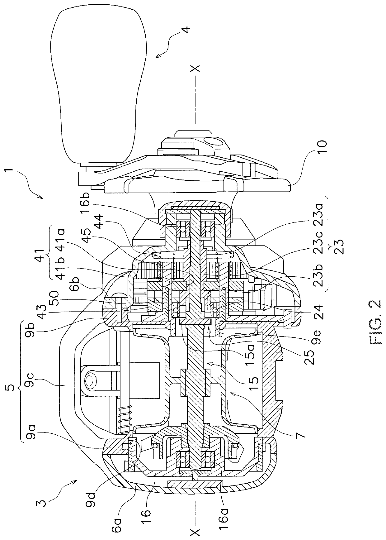
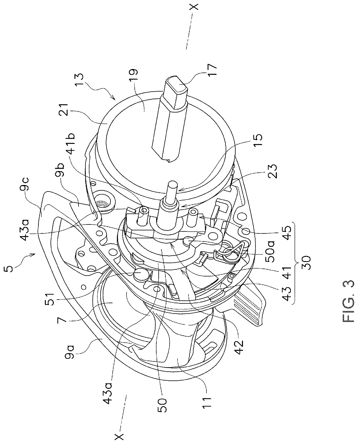
As illustrated in FIG. 1, a dual-bearing reel 1 of an embodiment of the present disclosure includes a reel body 3 that can be mounted on a fishing rod, a handle 4 disposed on the side of the reel body 3 for rotating a spool, and a spool 7 (refer to FIG. 2) rotatably mounted on the reel body 3. As illustrated in FIG. 2, the dual-bearing reel 1 further includes a clutch mechanism 25 capable of connecting the handle 4 and the spool 7 and releasing the connection between the handle 4 and the spool 7.

It should be noted that in the following description, the rotational axis of the spool 7 is referred to as a “spool axis X”. Also, the term “spool shaft direction” indicates an extending direction of the spool axis X and a direction along the spool axis x, whereas the term “circumferential direction” (rotational direction) indicates a circumferential direction about the spool axis X. Additionally, a direction away from the spool axis X is referred to as a “radial direction”.

<Reel Body>

A...


PUM


Abstract

A dual-bearing reel having a clutch mechanism for connecting a handle and a spool and releasing a connection between the handle and the spool is disclosed. The dual-bearing reel includes a metal frame, a clutch yoke, and a guide member made of resin. The metal frame supports a handle shaft of the handle. The clutch yoke is configured to switch the clutch mechanism between a connected state and a disconnected state. The guide member includes a main body part to be mounted on the frame, and a support part integrally formed with the main body part to guide the clutch yoke in an axial direction along an axis of the spool.

Description

CROSS-REFERENCE TO RELATED APPLICATIONSThis application claims priority to Japanese Patent Application No. 2018-065758, filed Mar. 29, 2018. The contents of that application are incorporated by reference herein in their entirety.BACKGROUNDTechnical FieldThe present disclosure relates to a dual-bearing reel, and more particularly to a dual-bearing reel having a clutch mechanism for connecting a handle and a spool and releasing the connection between the handle and the spool.Background InformationA clutch mechanism is disposed between a handle and a spool in a dual-bearing reel (refer to, for example, Japanese Laid-open Patent Application Publication No. 2010-172203). The clutch mechanism connects and disconnects the handle and the spool. The clutch mechanism includes a clutch yoke and a support member for supporting the clutch yoke.For example, Japanese Laid-open Patent Application Publication No. 2010-172203 discloses a support member in which two support parts and a main body part ...

Claims


Application Information

Patent Timeline
Patent Type & Authority Patents(United States)
IPC IPC(8): A01K89/01A01K89/015
CPCA01K89/0189A01K89/0193A01K89/015A01K89/0192A01K89/033A01K89/0186
Inventor BIN ISMAIL, MOHD SYAMSUL JOHARYBIN AHMAD, ABU SUPIAN
Owner SHIMANO COMPONENTS MALAYSIA
Learn More