
System for and method of gas cluster ion beam processing

Active Publication Date: 2008-05-27
TEL EPION
View PDF12 Cites 55 Cited by
  • Summary
  • Abstract
  • Description
  • Claims
  • Application Information

AI Technical Summary

Benefits of technology

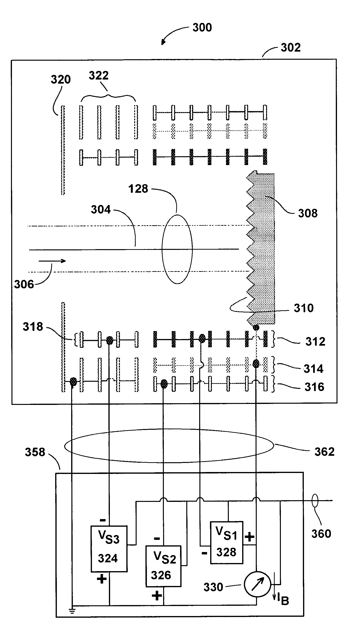
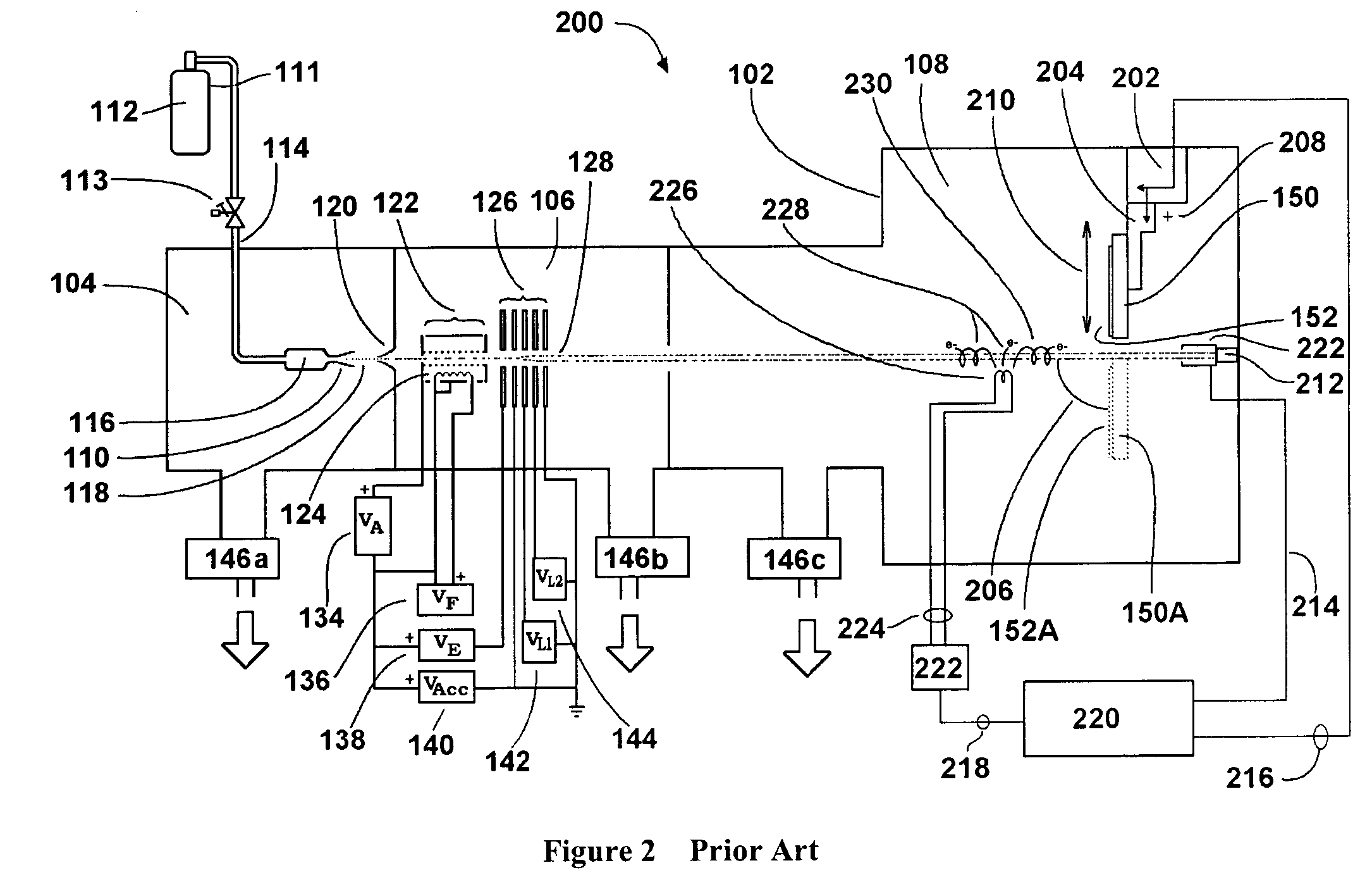
[0016]An improved GCIB neutralizing apparatus is comprised of an array of one or more thermionic filaments disposed around a GCIB axis. A cylindrical mesh acceleration electrode draws the thermionic electrons away from the filament(s), directing them toward the GCIB axis, helping to overcome the well known space-charge-limited-diode effect. A second cylindrical mesh deceleration electrode decelerates the accelerated electrons, causing them to travel into the GCIB with a very low energy. This acceleration / deceleration (Accel / Decel) electron source provides high electron emission, while delivering the space charge neutralizing electrons with very low energies. Thus, the electrons are especially effective at reducing GCIB space charge effects including the beam expansion problem that otherwise tends to limit the ability to deliver high GCIB currents to the workpiece. Additionally, the low energy electrons are transported by the beam potential-well to the workpiece to neutralize any charging that might otherwise tend to occur at the workpiece. Because copious quantities electrons are available, beam induced charging is minimal. Because the electrons have very low energies due to their Accel / Decel generation, they do not tend to charge the workpiece excessively negatively if the beam momentarily fluctuates. Thus, both positive and negative workpiece charging is limited to less than a few volts. The effective space charge neutralization in the GCIB results in the ability to transport larger GCIB currents. The larger GCIB currents cause an increased mass flow of gas clusters to the workpiece and to the beam current measuring device.
[0017]To avoid impairment of beam current measurement accuracy due to the large gas load that is accordingly released in the beam current measuring device, an improved faraday cup is utilized. The improved faraday cup is vented to facilitate the efficient removal of the beam-transported gas by the system's vacuum pumping system. It also has a novel biasing scheme and geometry that reduces measurement errors that would otherwise result. The improved faraday cup is cylindrical and consists of flat disk-electrodes stacked together with gaps between them to allow the beam transported gas to escape. The spacing between the disks is smaller than their radial extent so that electrical suppression fields fill the gaps. The suppression rings nearest the beam strike plate are biased by a supply with the positive terminal connected to the metering circuit. These rings suppress secondary electrons from the target plate and at the same time collect ions produced by charge exchange. Since the bias field needed to suppress to the center of the beam necessitates several kilovolts of bias, secondary ions striking the floating suppression ring set can generate secondary electrons, a portion of which could potentially escape between the rings. To collect these electrons an intermediate ring set is connected to the faraday cup strike plate and a slight negative bias is added on the outside rings opposite these intermediate rings. To encourage gas to escape laterally from the faraday cup, the strike plate incorporates grooving on its surface, preferably concentric circular grooves.

Problems solved by technology

Thus, both positive and negative workpiece charging is limited to less than a few volts.

Method used


Image

  • System for and method of gas cluster ion beam processing
  • System for and method of gas cluster ion beam processing
  • System for and method of gas cluster ion beam processing

Examples


Embodiment Construction

[0026]Preferred embodiments of the present invention will now be described with reference to the several figures of the drawing.

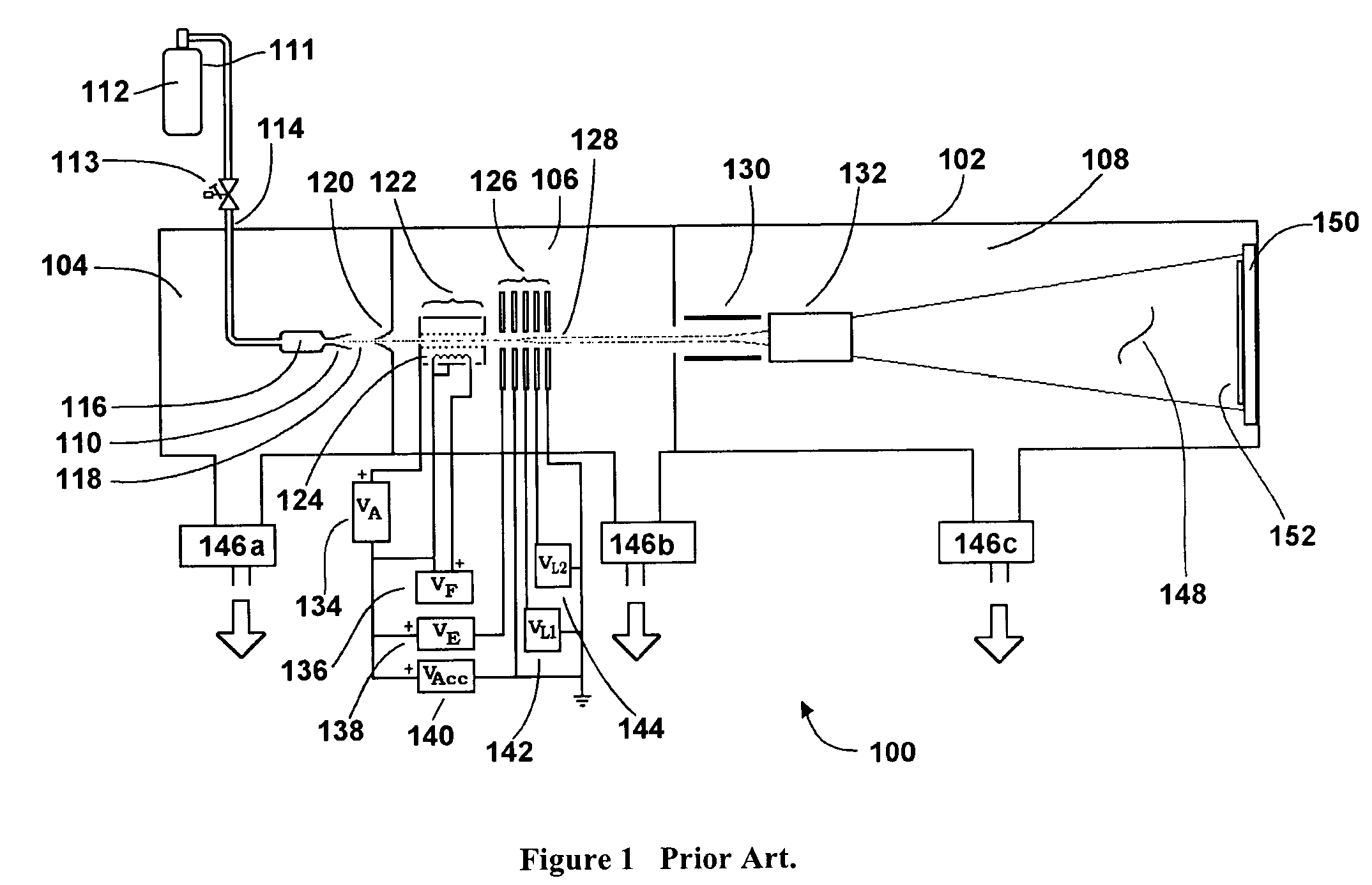
[0027]FIG. 1 shows a schematic of the basic elements of a typical configuration for a GCIB processor 100 of a form known in prior art, and which may be described as follows: a vacuum vessel 102 is divided into three communicating chambers, a source chamber 104, an ionization / acceleration chamber 106, and a processing chamber 108. The three chambers are evacuated to suitable operating pressures by vacuum pumping systems 146a, 146b, and 146c, respectively. A condensable source gas 112 (for example argon or N2) stored in a gas storage cylinder 111 is admitted under pressure through gas metering valve 113 and gas feed tube 114 into stagnation chamber 116 and is ejected into the substantially lower pressure vacuum through a properly shaped nozzle 110. A supersonic gas jet 118 results. Cooling, which results from the expansion in the jet, causes a portion of the ...


PUM

PropertyMeasurementUnit
Currentaaaaaaaaaa
Electrical conductivityaaaaaaaaaa
Transparencyaaaaaaaaaa

Abstract

System and method of gas-cluster ion beam processing is realized by incorporating improved beam and workpiece neutralizing components. Larger GCIB current transport is enabled by low energy electron neutralization of space charge of the GCIB. The larger currents transport greater quantities of gas in the GCIB. A vented faraday cup beam measurement system maintains beam dosimetry accuracy despite the high gas transport load.

Description

CROSS REFERENCE TO RELATED APPLICATIONS[0001]This application claims the benefit of priority to U.S. Provisional Application Ser. No. 60 / 412,931, filed Sep. 23, 2002, and entitled “Improved Gas Cluster Ion Beam Processing and Apparatus Therefor” which is incorporated herein by reference.BACKGROUND OF THE INVENTION[0002]The present invention relates generally to the formation of and application of increased-current gas-cluster ion beams (GCIB's) for processing the surfaces of workpieces, and, more particularly to reducing space charge effects in GCIB's, reducing workpiece charging, and to improving the measurement accuracy of GCIB currents and doses.[0003]The use of GCIB's for processing surfaces is known (see for example, U.S. Pat. No. 5,814,194, Deguchi et al.) in the art. For purposes of this discussion, gas clusters are nano-sized aggregates of materials that are gaseous under conditions of standard temperature and pressure. Such clusters typically consist of aggregates of from a...

Claims


Application Information

Patent Timeline
IPC IPC(8): C23C16/00A61N5/00G21G5/00C23C16/452H01J3/14H01J27/00H01J37/02H01J37/08H01J37/317
CPCC23C16/452H01J37/026H01J37/317H01J37/08H01J2237/0812H01J2237/0041
Inventor MACK, MICHAEL E.
Owner TEL EPION
Learn More