
Magnetic disk drive having a suspension mounted transmission line including read and write conductors and a lower conductor

a technology of suspension mount and transmission line, which is applied in the field of magnetic disk drives, can solve the problems of affecting the operation of the device, and the wiring is unlikely to be applied to the wiring near the head, so as to reduce the loss of transmission lines, improve the electrical properties, and improve the effect of vibration properties

Inactive Publication Date: 2008-01-15
HITACHI GLOBAL STORAGE TECH JAPAN LTD
View PDF16 Cites 115 Cited by
  • Summary
  • Abstract
  • Description
  • Claims
  • Application Information

AI Technical Summary

Benefits of technology

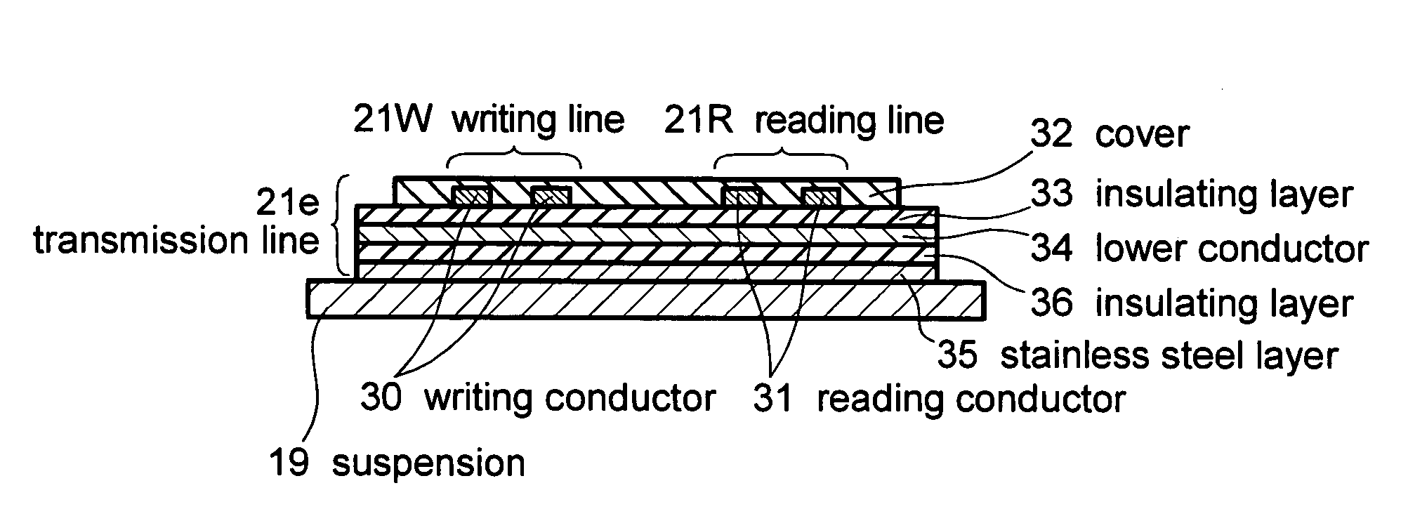
[0004]Embodiments of the present invention provide a new technology is achievable in regards to the transmission line structure of the magnetic disk drive. The magnetic disk drive has improved electrical properties owing to a reduction in the loss of transmission line, improved vibration properties owing to a reduction in the stiffness of wiring around the head, and a flat impedance in the transmission line.
[0006]In the conventional transmission line mentioned above, the lower conductor of stainless steel will have increased transmission loss if it is made thin enough to be applied to the wiring near the head. This phenomenon will be explained later. Thus, in the conventional transmission line based on the technology disclosed in Japanese Patent Laid-open No. 2002-237016, reducing loss in the transmission line is incompatible with reducing rigidity in wiring near the head. A solution to this problem is being sought.

Problems solved by technology

The conventional transmission line mentioned above poses a problem with a considerable transmission loss because it has the lower conductor of stainless steel formed under the conductors of the writing transmission line and the reading transmission line.
However, if the copper sheet member (or the lower conductor) is as thick as 500 μm, as mentioned in Japanese Patent Laid-open No. 2002-237016, it is unlikely to be applied to the wiring near the head because of its high rigidity.
However, such a wiring is incapable of impedance control and vulnerable to external noise.
In the conventional transmission line mentioned above, the lower conductor of stainless steel will have increased transmission loss if it is made thin enough to be applied to the wiring near the head.
Thus, in the conventional transmission line based on the technology disclosed in Japanese Patent Laid-open No. 2002-237016, reducing loss in the transmission line is incompatible with reducing rigidity in wiring near the head.

Method used


Image

  • Magnetic disk drive having a suspension mounted transmission line including read and write conductors and a lower conductor
  • Magnetic disk drive having a suspension mounted transmission line including read and write conductors and a lower conductor
  • Magnetic disk drive having a suspension mounted transmission line including read and write conductors and a lower conductor

Examples


Embodiment Construction

[0030]The invention will be described below in more detail with reference to the accompanying drawings, in which like reference characters designate like or corresponding parts throughout.

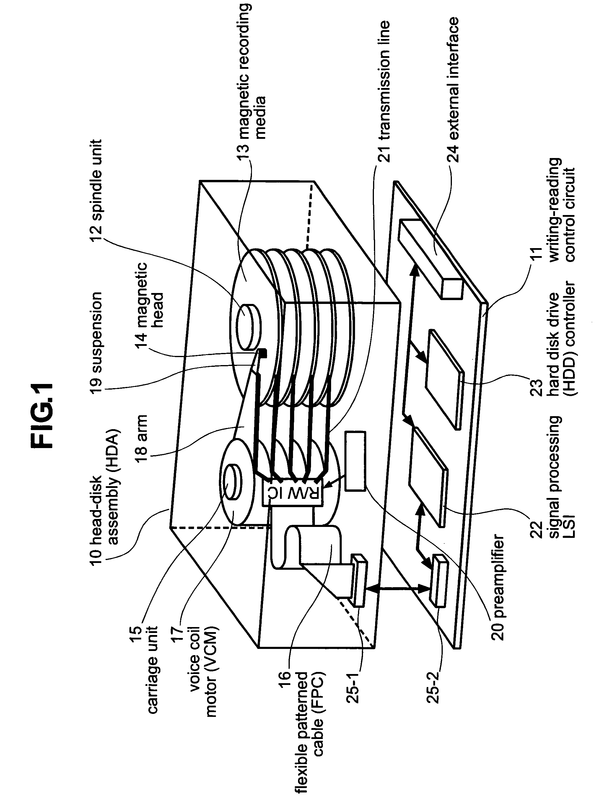
[0031]FIG. 1 illustrates the construction of the magnetic disk drive according to one embodiment of the present invention. The magnetic disk drive includes a head-disk assembly (HDA) 10 and a writing-reading control circuit 11.

[0032]The HDA 10 includes a spindle unit 12 to which are attached magnetic recording media 13 in layers, and a carriage unit 15 on which are mounted magnetic heads 14 to write and read information to and from the magnetic recording media 13. They are enclosed in an aluminum base and covering.

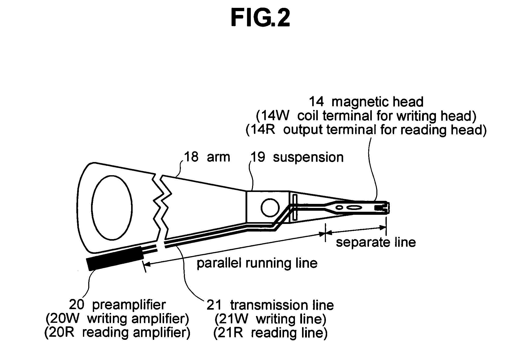
[0033]The carriage unit 15 includes a voice coil motor (VCM) 17 which moves the magnetic heads 14 for seeking and positioning over the magnetic recording media 13, arms 18, suspensions 19 attached respectively to the forward ends of the arms 18, magnetic heads 14 attached respectively to ...


PUM

PropertyMeasurementUnit
thickaaaaaaaaaa
thicknessaaaaaaaaaa
thicknessaaaaaaaaaa

Abstract

Embodiments of the invention provide a magnetic disk drive which has improved electrical properties owing to a reduction in the loss of transmission line, improved vibration properties owing to a reduction in the stiffness of wiring around the head, and a flat impedance in the transmission line. In one embodiment, a magnetic disk drive comprises a suspension; a magnetic head coupled with the suspension and configured to write and read information to and from a magnetic recording medium; and a transmission line disposed on the suspension to transmit writing and reading information to and from the magnetic head. The transmission line includes a writing line and a reading line, a lower conductor disposed underneath the writing line and the reading line, and an insulating layer interposed between the lower conductor and the writing and reading lines. The lower conductor comprises copper or copper-based alloy and has a thickness of substantially less than 25 μm, desirably about 2-12 μm, and more desirably about 5 μm.

Description

CROSS-REFERENCES TO RELATED APPLICATIONS[0001]This application relates to and claims priority from Japanese Patent Application No. 2003-170945, filed on Jun. 16, 2003.BACKGROUND OF THE INVENTION[0002]The present invention relates to a magnetic disk drive and, more particularly, to a technology which is effectively applicable to the transmission line structure to be mounted on the suspension for transmission of writing-reading signals to and from the magnetic head. The magnetic disk drive which is designed to write and read a large quantity of data in a limited space within a short time needs a technology to increase the recording density, a technology to increase the rate of data transmission, and a technology to increase the frequency for writing and reading. There is a type of magnetic disk drive meeting these requirements in which the line for transmission of writing and reading signals to and from the magnetic head is formed by printing on the suspension. This transmission line ...

Claims


Application Information

Patent Timeline
Patent Type & Authority Patents(United States)
IPC IPC(8): G11B5/48G11B5/60G11B21/21G11B33/08H05K1/02H05K1/05
CPCG11B5/4833G11B33/08H05K1/0253H05K1/0245H05K1/056H05K2201/09236H05K2201/09318G11B5/484G11B5/486A47C7/405A47C7/62A61H2023/0209A61H2201/0149A61H2201/5023A61H2201/5043A61H2203/0431A61H2205/081A61H2205/088A61N1/44A61N2/02
Inventor NISHIYAMA, NOBUMASA
Owner HITACHI GLOBAL STORAGE TECH JAPAN LTD
Learn More