
Method and apparatus for a self-aligned recessed access device (RAD) transistor gate

a technology of recessed access devices and transistor gates, which is applied in the direction of transistors, electrical devices, semiconductor devices, etc., can solve the problems of excessively small transistor channel width, transistor activation, and difficult electrical operation of transistors, and achieve the effect of reducing problems

Active Publication Date: 2007-10-16
MICRON TECH INC
View PDF9 Cites 83 Cited by
  • Summary
  • Abstract
  • Description
  • Claims
  • Application Information

AI Technical Summary

Benefits of technology

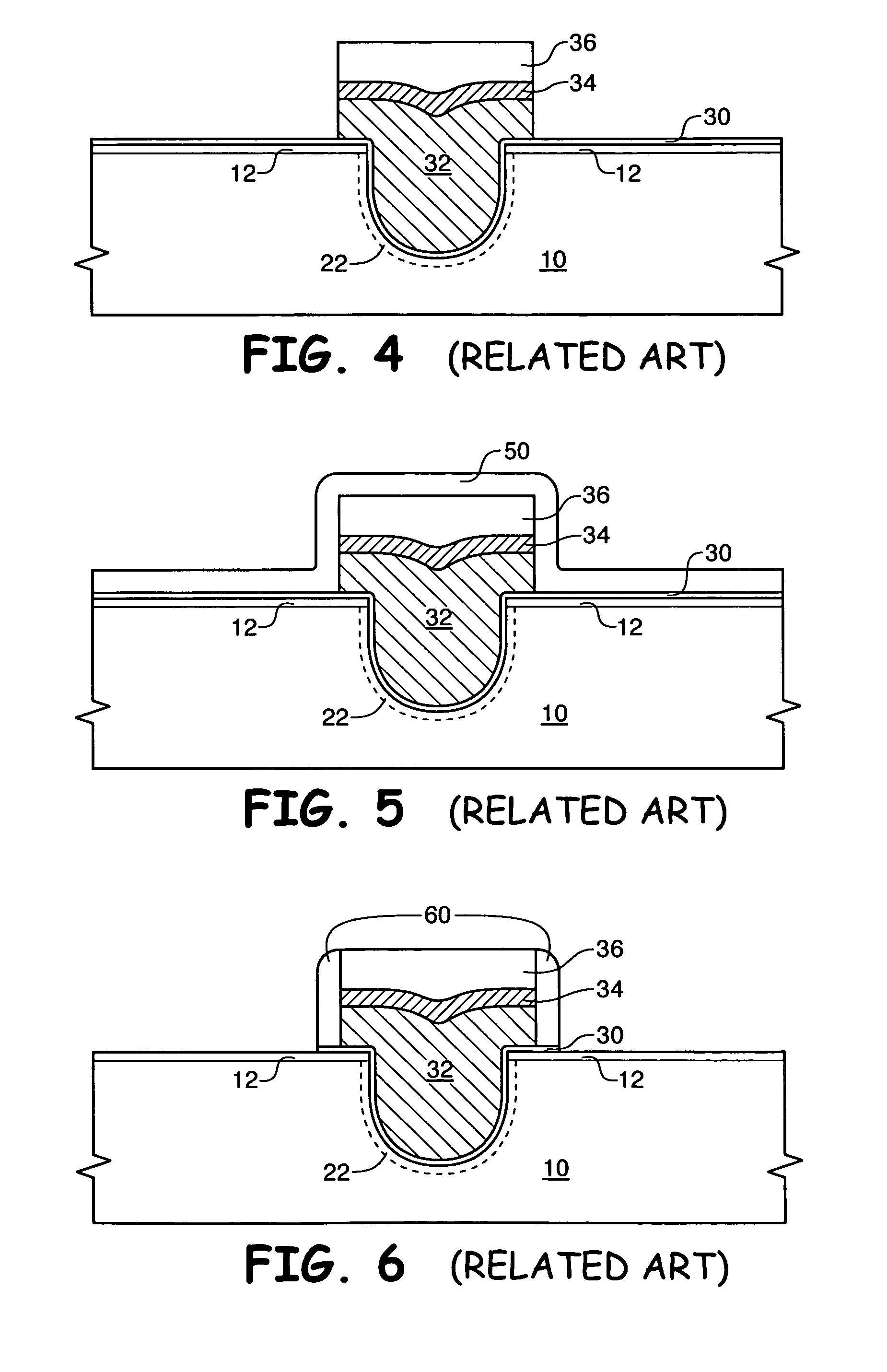
The present invention provides a new method for manufacturing semiconductor devices, particularly those with recessed access device (RAD) transistors. The method reduces problems associated with mask misalignment during the formation of the RAD transistor. The method includes steps of forming a pad oxide layer and a dielectric vertical spacing layer over a semiconductor wafer, etching a trench or opening in the wafer, implanting the wafer to form a channel region, and providing a gate oxide within the trench. Next, blanket gate layers are formed, including a doped polysilicon layer, a silicide layer, and a capping layer. The capping layer, silicide layer, and polysilicon layer are masked with a patterned photoresist layer, which defines the transistor gate. The exposed portions of the layers are overetched to prevent removal of the polysilicon layer from over the vertical spacing layer. An implant may be performed to adjust the source / drain regions, and a blanket conformal spacer layer is formed over the transistor gate and over the vertical spacing layer. A vertical etch is performed to expose the semiconductor wafer, and the process continues as known in the art to complete the semiconductor device. The method provides additional misalignment tolerance of the mask and reduces problems associated with mask misalignment.

Problems solved by technology

As feature sizes decrease, the electrical operation of the transistor becomes more difficult.
One contributing factor to this difficulty is known as the “short channel effect” in which the width of the transistor channel becomes excessively small due to miniaturization.
This may result in the transistor activating even though a threshold voltage (Vt) has not been applied to the gate.
A not-infrequent problem with semiconductor device formation, particularly with decreasing feature sizes, is misalignment of a photoresist mask.
The transistor of FIG. 10 will have poor electrical operation and may even be nonfunctional.

Method used


Image

  • Method and apparatus for a self-aligned recessed access device (RAD) transistor gate
  • Method and apparatus for a self-aligned recessed access device (RAD) transistor gate
  • Method and apparatus for a self-aligned recessed access device (RAD) transistor gate

Examples


Embodiment Construction

[0022]The term “wafer” is to be understood as a semiconductor-based material including silicon, silicon-on-insulator (SOI) or silicon-on-sapphire (SOS) technology, doped and undoped semiconductors, epitaxial layers of silicon supported by a base semiconductor foundation, and other semiconductor structures. Furthermore, when reference is made to a “wafer” in the following description, previous process steps may have been utilized to form regions or junctions in or over the base semiconductor structure or foundation. Additionally, when reference is made to a “substrate assembly” in the following description, the substrate assembly may include a wafer with layers including dielectrics and conductors, and features such as transistors, formed thereover, depending on the particular stage of processing. In addition, the semiconductor need not be silicon-based, but may be based on silicon-germanium, silicon-on-insulator, silicon-on-sapphire, germanium, or gallium arsenide, among others. Fur...


PUM


Abstract

A method used in fabrication of a recessed access device transistor gate has increased tolerance for mask misalignment. One embodiment of the invention comprises forming a vertical spacing layer over a semiconductor wafer, then etching the vertical spacing layer and the semiconductor wafer to form a recess in the wafer. A conductive transistor gate layer is then formed within the trench and over the vertical spacing layer. The transistor gate layer is etched, which exposes the vertical spacing layer. A spacer layer is formed over the etched conductive gate layer and over the vertical spacing layer, then the spacer layer and the vertical spacing layer are anisotropically etched. Subsequent to anisotropically etching the vertical spacing layer, a portion of the vertical spacing layer is interposed between the semiconductor wafer and the etched conductive transistor gate layer in a direction perpendicular to the plane of a major surface of the semiconductor wafer.

Description

FIELD OF THE INVENTION[0001]This invention relates to the field of semiconductor manufacture and, more particularly, to a method used in the formation of a recessed access device (RAD) transistor gate, and a structure for a RAD transistor gate.BACKGROUND OF THE INVENTION[0002]Manufacture of various semiconductor devices such as memory devices, logic devices, and microprocessors has the common goal of miniaturization. As feature sizes decrease, the electrical operation of the transistor becomes more difficult. One contributing factor to this difficulty is known as the “short channel effect” in which the width of the transistor channel becomes excessively small due to miniaturization. This may result in the transistor activating even though a threshold voltage (Vt) has not been applied to the gate.[0003]One type of transistor which has been developed to overcome the short channel effect of a conventional transistor by forming a wider channel in the same horizontal space is referred to...

Claims


Application Information

Patent Timeline
Patent Type & Authority Patents(United States)
IPC IPC(8): H01L21/8238
CPCH01L21/26586H01L29/7834H01L29/66659H01L29/66621H01L29/4236H01L29/42368H01L29/78
Inventor JUENGLING, WERNER
Owner MICRON TECH INC
Learn More