
Method and apparatus for whole-body, three-dimensional, dynamic PET/CT examination

a dynamic pet/ct and whole-body technology, applied in the field of electronic and apparatus detectors for detecting, to achieve the effect of reducing radiation dosage requirements, increasing sensitivity, and reducing costs

Inactive Publication Date: 2007-02-20
CROSETTO DARIO B
View PDF8 Cites 105 Cited by
  • Summary
  • Abstract
  • Description
  • Claims
  • Application Information

AI Technical Summary

Benefits of technology

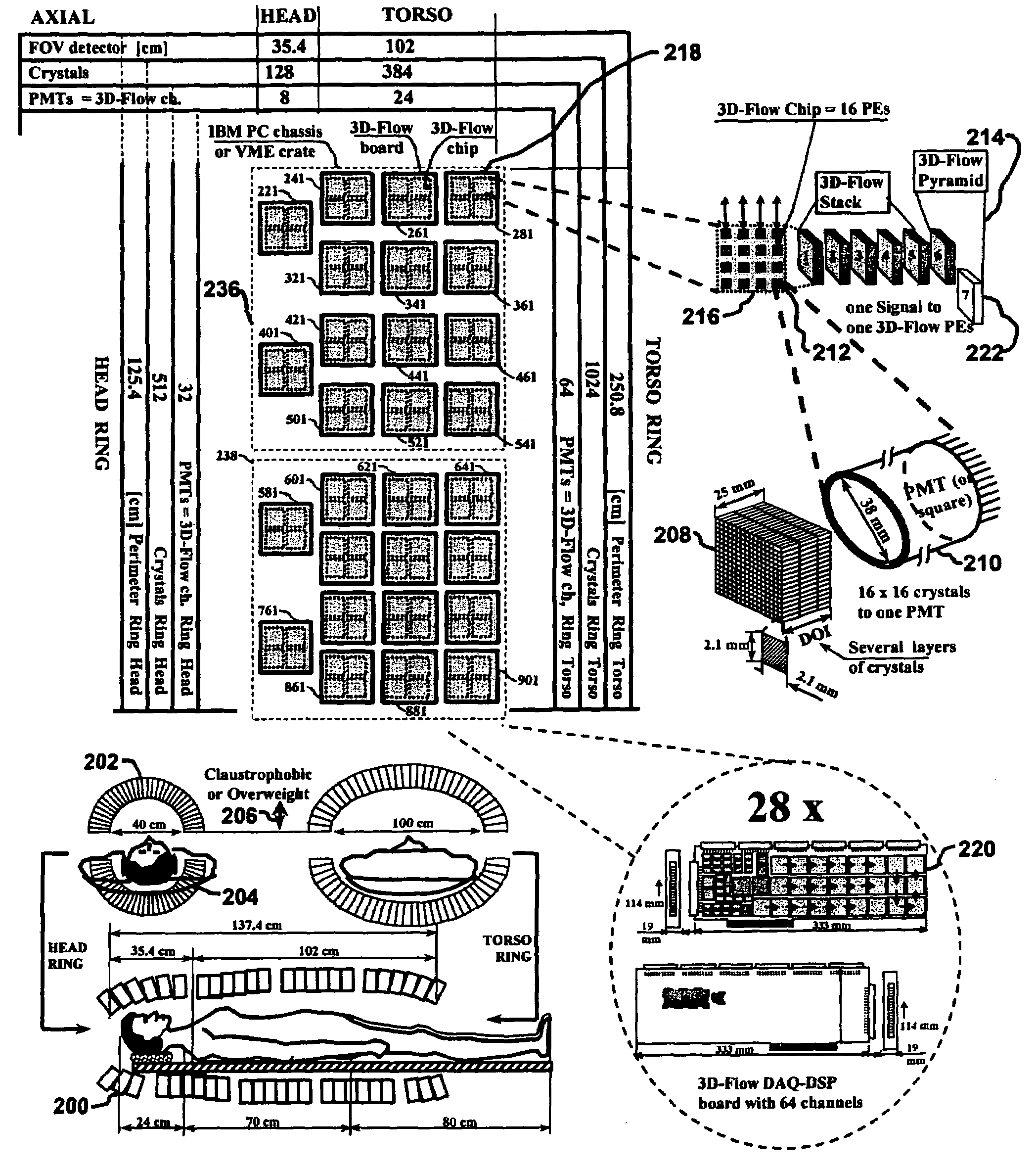
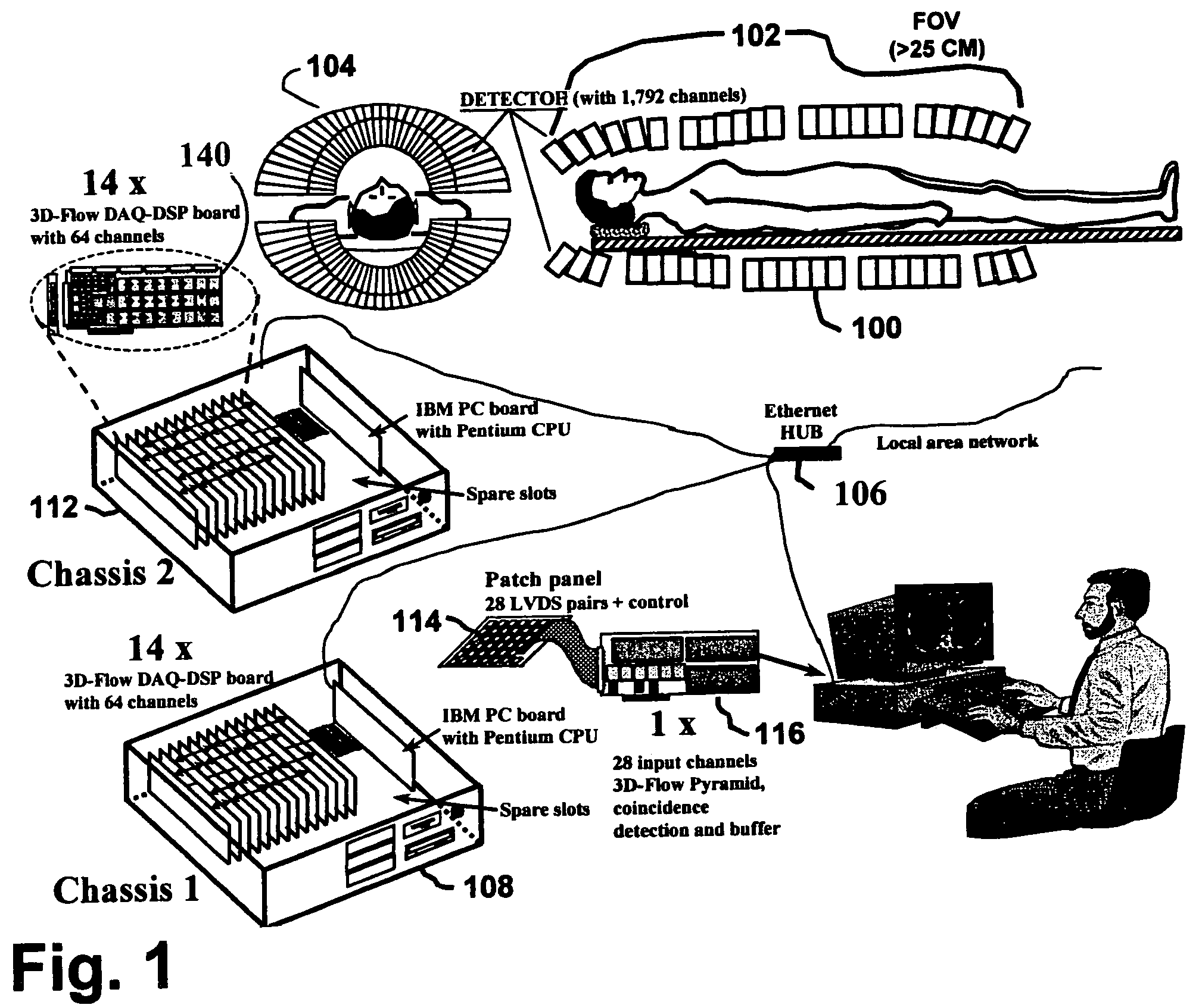
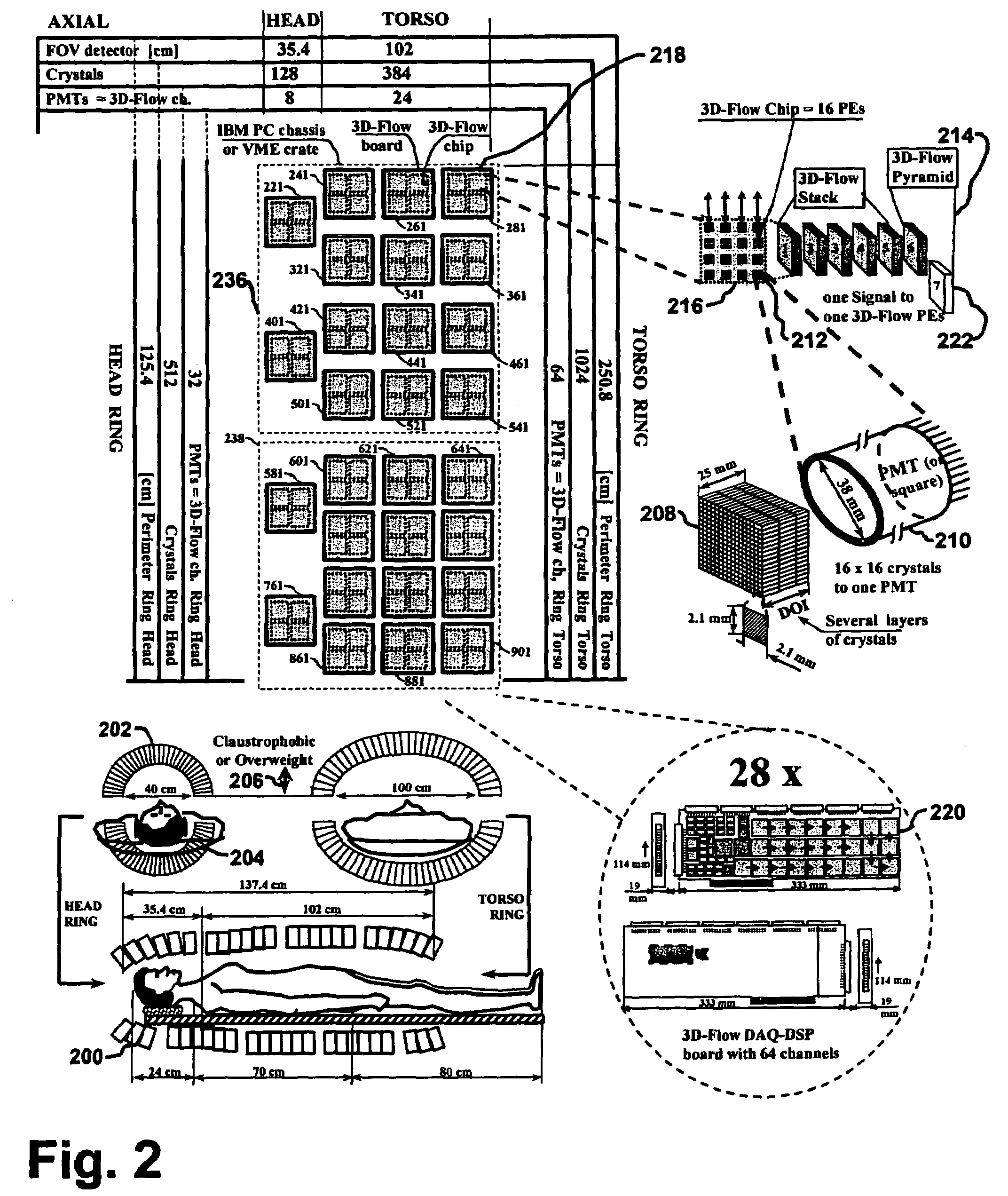
[0042]The 3-D Complete Body Scan (3D-CBS) medical imaging device combines the features of anatomical imaging capability of the Computed Tomography (CT) with the functional imaging capability of the Positron Emission Tomography (PET). FIG. 1 shows the layout of the components of the 3D-CBS, and FIG. 2 show the logical and physical layout of the 3D-CBS. More specifically, a detector 100 is coupled to produce electrical signal representing detected photons to an image processing and data acquisition board 140. Data acquisition board 140 is one of 14 boards per chassis 108, 112 in the described embodiment of the invention. In the described system, 64 channels per data acquisition board 140 are used to transmit the electrical signals. Each data acquisition board 140 has 64 inputs and one output channel. Moreover, one chassis 112 includes 14 data acquisition boards 140. Chassis 112 produces 14 output signals, one per data acquisition board, that are transmitted, e.g., over a local area network and hub 104, to a patch panel 114 that in turn transmits the signals to a pyramid board 116 that generates an image for display for the operator. FIG. 1 also displays some functional components of the layout and design. Detector 100 has distinct features in terms of not only extending the length of the crystal detectors or “field of view”102 to cover a significant length of the body (more than 25 cm of detectors). Field of view 102 is geometrically shaped to fit the contours of the body, with a narrowing near the head, to allow for a complete scan at once and to cost effectively increase the length of the detectors and to minimize the distance between the detectors and the emitting source (in FIG. 1, the human body). The design will allow field of view 102 to not only extend beyond 25 cm, but to be over one meter in length. The body fitting contour of detector 100 also enables the simplest possible PET electronics necessary to operate PET calculations in real time. Elliptical crystal design 104 also cost effectively increases the length of the detectors and minimizes the distance between the detectors and the emitting source. The space between the upper half of elliptical crystal design 104 and the lower half of elliptical crystal design 104 demonstrates the open hatch design of the 3D-CBS (3D Complete Body Scan), which can either be closed for greater photon detection efficiency or opened to accommodate the patient's claustrophobia or weight (further explained in FIG. 2).

Problems solved by technology

The advent of PET in the last 25 years has not had a striking impact in hospital practice and has not been widely used because the electronics with the capability of fully exploiting the superiority of the PET technique has never been designed.
Low efficiency in detecting photons without the capability of fully extracting the photon's properties gives poor images that cannot show small tumors, making the device unsuitable for early detection.
In addition, it requires high radiation to the patient, which prevents annual examination; and it requires more imaging time, which limits its use to fewer patients per hour, driving the examination cost very high.
This is used to limit the number of photons hitting the detector (in particular for body scan where Compton scattering is more numerous than in a smaller volume head-scan) because the electronics cannot handle the unregulated rate of photons hitting the detector.
The real-time algorithm of current PET cannot thoroughly process all the information necessary to separate a good event from bad events.
Using the current CTI / Siemens and GE approach, the complexity of the electronics would increase enormously, or, alternatively, one would have to drop many photons from being checked.
In that case, however, no significant advantage is provided to the patient, because the radiation and the cost have not been lowered.
Although the CT images are of good quality at the expenses of a relatively high x-ray beam (which should be lowered in order to lower the risk to the patient), the PET images are of poor quality because only a few emitted photons from the patient's body are captured by the PET detector.
Other deficiencies of the current PET machines are: low coverage of the entire body, false positives, high radiation dose, slow scanning, high examination costs.
Briefly, following is a list of the main areas of inefficiencies in the current PET which prevent maximum exploitation of positron emission technology.1. The image quality of current PET is poor because it has:a. a short FOV, limit by a non efficient electronics that do not offset the cost of the detector if the FOV were increased (see also next section about the false positive and false negatives);b. no accurate time-stamp assigned to each photon (a) limiting the detection of neighboring photons emitted within a short time interval, (b) causing long dead-time of the electronics and (c) increasing randoms, or photons in time coincidence belonging to two different events, (most PETs do not have any photon time-stamp assignment);c. analog signal processing on the front-end electronics limiting photon identification because of poor extraction of the characteristics of the incident photon and absence of the capability to improve signal-to-noise (S / N) ratio;d. detector boundary limitation to 2×2 PMT blocks, no correlation between signals from neighboring detector blocks, no full energy reconstruction of the photons that hit the detector, (most of current PET do not attempt to make any energy reconstruction of the event, but take decisions in accepting or rejecting first a photon and later an event based on the threshold of a single signal).e. dead-time of the electronics.
Dead-time of the electronics is due to any bottleneck (e.g., multiplexing of data from many lines to a single line, saturation on input, processing, saturation on output) present at any stage of the electronics;f. saturation of the electronics at the input stage due to its inability to detect and process two nearby photons that hit the detector within a short time interval;g. costly and inefficient coincidence detection circuit (most current PET [20], [18] have a coincidence detection circuit that tests for coincidence all possible combinations of the Lines of Response (LOR) passing through the patient's body).
This approach adds unnecessary complexity to the electronics of the current PET and makes it unreasonably costly to build a circuit with an acceptable efficiency when more detector elements are added to the detector (which is required in extending the FOV);h. saturation of the electronics at the output stage due to the limiting architecture of the coincidence detection circuit (See Section 5.6.8.1.4);i.
Poor measurement of the attenuation of different tissues at different locations in a patient's body.
The short FOV and the inefficient electronics allow to accumulate fewer than 2 photons in coincidence every 10,000 emitted.
This inefficiency requires to administer necessarily high radiation dosage to the patient in order to keep the examination time within an hour.4. The slow scanning time is because of the short FOV of the current PET and of the low efficiency of the electronics.
The limited efficiency mentioned above of 2 out of 10,000 requires long acquisition time.
Examinations longer than one hour are unacceptable because (a) the biological process desired to observe and the radioisotope decay activity would be over, (b) the patient would be uncomfortable, and (c) the cost would be even higher that what it already is;5. The current high cost of the examination is due to:the high cost of the huge dose of radioisotope required;the slow scanning time that allows only six to seven patients per day to be examined; andthe cost of highly paid personnel who must operate the slow machine.

Method used


Image

  • Method and apparatus for whole-body, three-dimensional, dynamic PET/CT examination
  • Method and apparatus for whole-body, three-dimensional, dynamic PET/CT examination
  • Method and apparatus for whole-body, three-dimensional, dynamic PET/CT examination

Examples


Embodiment Construction

6.1 Multimodality: Design of a Multimodal PET / SPECT / CT 3D-Flow Based System

6.1.1 Description and Requirements of a Multimodality PET / SPECT / CT Device

[0223]The combination of several medical imaging modalities in a single device is referred to as multimodality. It helps the physician in clinical examinations to see in a single image several pieces of information which before could only be acquired by having the patient go through several medical examinations.

[0224]The combination of the PET device with an x-ray-computed tomograph (CT) scan provides, by means of the CT, the anatomical information that helps to identify the organs in the body, and it provides, by means of the PET, the functional information that provides real-time imaging of the biological process at the molecular level. (In some area, such as the one showing increased brain activity caused by sensorimotor or cognitive stimuli, functional Magnetic Resonance Imaging (fMRI), shows image contrast in regions where oxygen is...


PUM


Abstract

A body scanning system includes a CT transmitter and a PET configured to radiate along a significant portion of the body and a plurality of sensors configured to detect photons along the same portion of the body. In order to facilitate the efficient collection of photons and to process the data on a real time basis, the body scanning system includes a new data processing pipeline that includes a sequentially implemented parallel processor that is operable to create images in real time notwithstanding the significant amounts of data generated by the CT and PET radiating devices.

Description

1 RELATED APPLICATIONS[0001]This application is a continuation of and claims priority to co-pending U.S. non-provisional patent application Ser. No. 10 / 185,904, filed June 27, 2002 and entitled “Method and Apparatus for Whole-Body, Three-Dimensional, Dynamic PET / CT Examination”, which claims benefit of provisional application Ser. No. 60 / 301,545, filed Jun. 27, 2001 and entitled “Method and Apparatus for Whole-Body Annual PET / CT Examination” and provisional application Ser. No. 60 / 309,018, filed Jul. 31, 2001 and entitled “Method and Apparatus for Whole-Body, Three-Dimensional, Dynamic PET / CT Examination”, the disclosure of each of which is incorporated herein in its entirety.2 FIELD OF THE INVENTION[0002]The present invention relates to: computer architecture, system architecture, parallel-processing, pipelining, multiplexing, pattern recognition algorithms, detector assembly and nuclear medicine imaging system and in particular to the electronics and detectors of apparatus detecti...

Claims


Application Information

Patent Timeline
IPC IPC(8): G01T1/00
CPCG01T1/1611G01T1/1615A61B6/037G01T1/2985G01T1/1642
Inventor CROSETTO, DARIO B.
Owner CROSETTO DARIO B
Learn More