
Method of forming oxide layer using atomic layer deposition method and method of forming capacitor of semiconductor device using the same

a technology of atomic layer and forming method, which is applied in the direction of coating, transistor, chemical vapor deposition coating, etc., can solve the problems of reducing threshold voltage, increasing gate leakage current, and affecting so as to improve the stability and reliability of the resulting semiconductor device, improve the deposition characteristics, and improve the step coverage

Inactive Publication Date: 2006-12-19
SAMSUNG ELECTRONICS CO LTD
View PDF13 Cites 78 Cited by
  • Summary
  • Abstract
  • Description
  • Claims
  • Application Information

AI Technical Summary

Benefits of technology

The present invention provides methods for forming an oxide layer using atomic layer deposition (ALD) that have improved deposition rates and better deposition characteristics. These methods involve applying a precursor with an amino functional group to a substrate and chemisorbing a portion of the precursor onto the substrate. An oxidant is then introduced to react with the chemisorbed precursor to form an atomic layer of oxide on the substrate. The methods may be used to form thin films on semiconductor devices, including capacitors and gate insulation layers. The use of ALD allows for the formation of high-quality oxide layers with improved deposition rates and reduced pattern loading effects.

Problems solved by technology

However, reducing the thickness of the gate insulation layer can result in several problems, such as increased gate leakage current, penetration of the gate by dopants or other impurities, reduced threshold voltages, etc.
When the cell capacitance decreases, the readability of data stored in the memory cell deteriorates, the likelihood of soft errors increases and the memory device becomes difficult to operate satisfactorily at low voltage.
However, when manufacturing a dynamic random access memory (DRAM) having a degree of integration necessary to achieve a capacity of about one gigabit or more, it is difficult to achieve a sufficiently high capacitance by employing the suggested methods.
As a result, the semiconductor device may receive or incur an unfavorable thermal budget.
In addition, thin films formed by the CVD methods tend to suffer from a degree of thickness non-uniformity and lower step coverage percentages than desired for highly integrated devices.
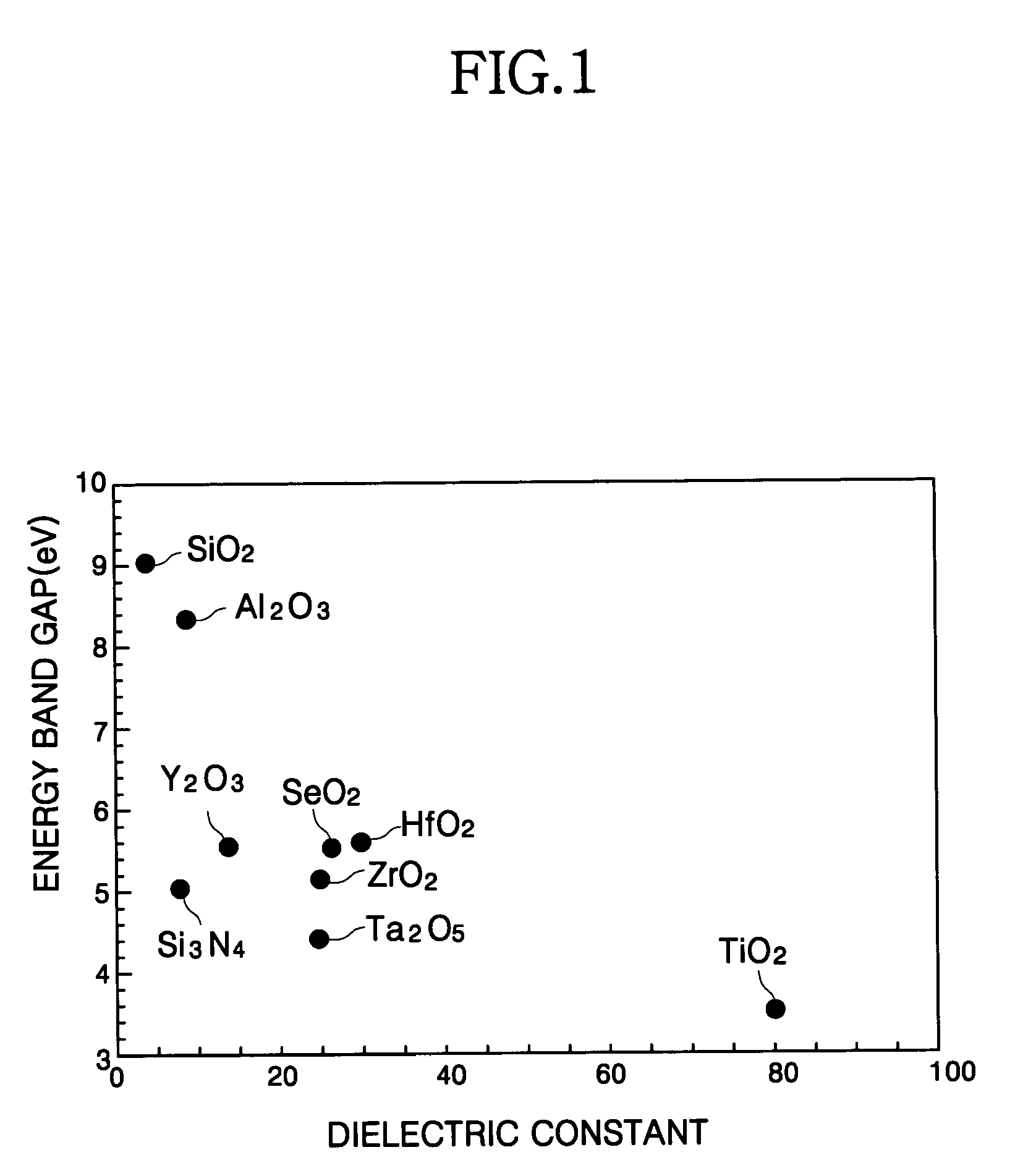
However, because Ta2O5 has a relatively low energy band gap, a capacitor having a dielectric layer formed using Ta2O5 tends to exhibit a very high leakage current.
However, according to these disclosures, achieving an HfO2 layer having good step coverage on structures having a high aspect ratio remain difficult.

Method used


Image

  • Method of forming oxide layer using atomic layer deposition method and method of forming capacitor of semiconductor device using the same
  • Method of forming oxide layer using atomic layer deposition method and method of forming capacitor of semiconductor device using the same
  • Method of forming oxide layer using atomic layer deposition method and method of forming capacitor of semiconductor device using the same

Examples


Embodiment Construction

[0043]Hereinafter, exemplary embodiments of the present invention will be described in detail.

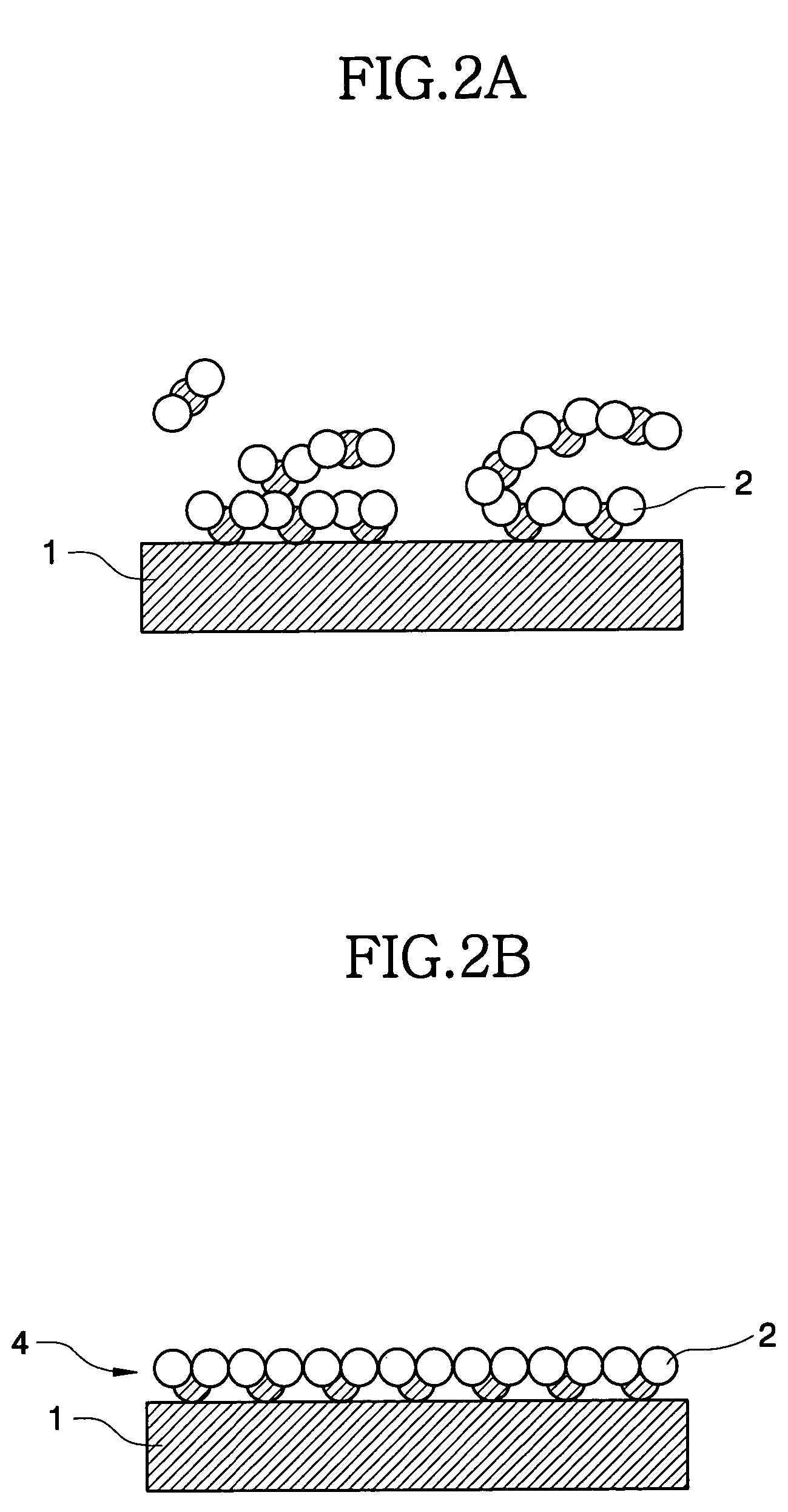
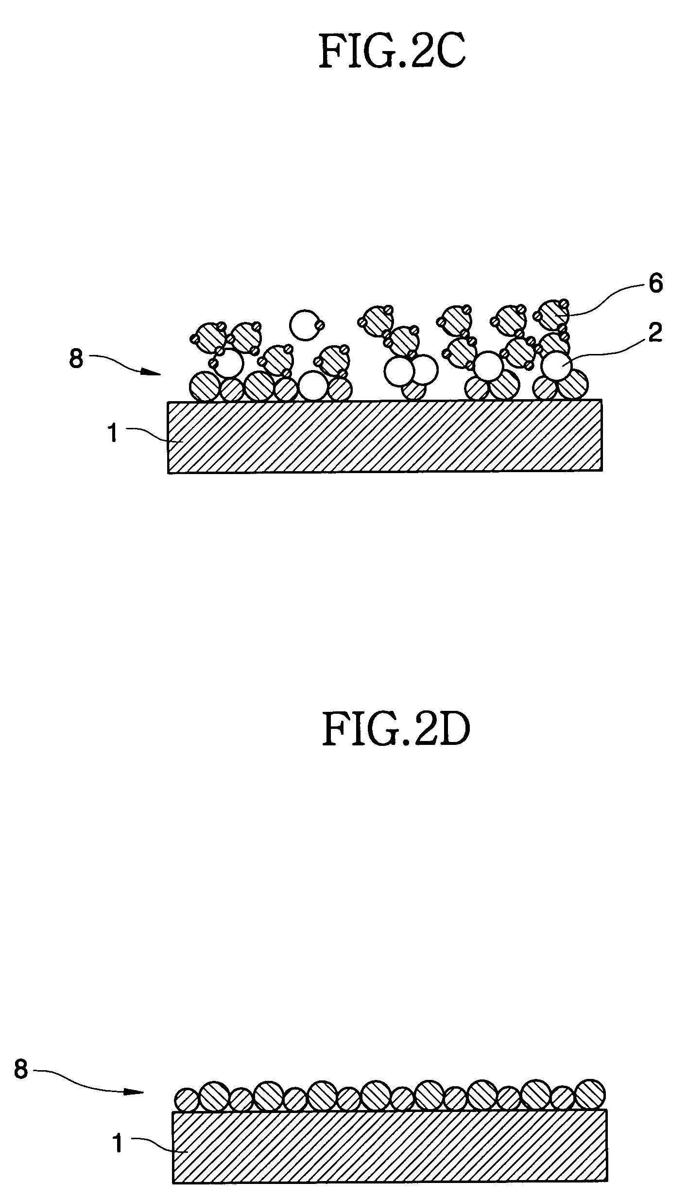
[0044]FIGS. 2A to 2E are cross-sectional views for explaining an exemplary embodiment of forming an oxide layer using an atomic layer deposition method. As illustrated in FIG. 2A, a substrate 1, such as a silicon wafer, is placed in a chamber in which a temperature of from about 100° C. to about 500° C. is maintained. The pressure of the chamber is controlled to about 0.4 Torr or less. In an exemplary embodiment, the temperature range is from about 150° C. to about 350° C. A precursor containing one central metal or semimetal element and an amino functional group is introduced into the chamber using an inert carrier gas such as argon (Ar) or nitrogen (N2) at a flow rate of about 50–5000 sccm for about 1–3 seconds to form an absorption layer 2 on the substrate. In an exemplary embodiment, the flow rate of the inert gas is in a range of about 500–1500 sccm.

[0045]The precursor includes a compo...


PUM

PropertyMeasurementUnit
pressureaaaaaaaaaa
temperatureaaaaaaaaaa
dielectric constantaaaaaaaaaa

Abstract

In a method of forming an oxide layer using an atomic layer deposition and a method of forming a capacitor of a semiconductor device using the same, a precursor including an amino functional group is introduced onto a substrate to chemisorb a portion of the precursor on the substrate. Then, the non-chemisorbed precursor is removed. Thereafter, an oxidant is introduced onto the substrate to chemically react the chemisorbed precursor with the oxidant to form an oxide layer on the substrate. A deposition rate is fast and an oxide layer having a good deposition characteristic may be obtained. Also, a thin oxide film having a good step coverage and a decreased pattern loading rate can be formed.

Description

CROSS-REFERENCE TO RELATED APPLICATIONS[0001]This application claims priority under 35 U.S.C. § 119 from Korean Patent Application No. 2002-48720, filed on Aug. 17, 2002, the contents of which are herein incorporated by reference in its entirety.BACKGROUND OF THE INVENTION[0002]1. Field of the Invention[0003]The present invention relates to a method of forming an oxide layer and a method of forming a capacitor of a semiconductor device using such an oxide layer as the dielectric, and more particularly, to a method of forming an oxide layer using an atomic layer deposition (ALD) method and a method of forming a capacitor of a semiconductor device using the same.[0004]2. Description of the Related Art[0005]As the demand for highly integrated semiconductor devices having high operating speeds has continued to increase, the surface area of the semiconductor substrate dedicated to each memory cell has been gradually reduced. As the area of the memory cells is reduced, the horizontal area...

Claims


Application Information

Patent Timeline
Patent Type & Authority Patents(United States)
IPC IPC(8): H01L21/20H01L21/31H01L21/205C23C16/40C23C16/44C23C16/455H01L21/02H01L21/316H10B12/00
CPCC23C16/401C23C16/45553H01L21/02178H01L21/02181H01L21/022H01L21/0228H01L21/02304H01L21/31604H01L21/3162H01L21/3165H01L27/10817H01L27/10852H01L21/31683H01L28/91H10B12/318H10B12/033H01L21/02194H01L21/28556
Inventor LEE, YUN-JUNGPARK, IN-SUNGIM, GI-VINPARK, KI-YEONYEO, JAE-HYUN
Owner SAMSUNG ELECTRONICS CO LTD
Learn More