Method for increasing the interference resistance of a time frame reflectometer and a circuit device of implementing said method

a time-frame reflectometer and interference resistance technology, which is applied in the direction of engine lubrication, liquid/fluent solid measurement, reradiation, etc., can solve the problems of high vulnerability to interference in the form of high-frequency interference signals, the mistune of the quartz oscillator cannot be far enough, and the interference resistance of the time-frame reflectometer cannot be increased. , to achieve the effect of increasing the security against interference and improving the simple and economical

Inactive Publication Date: 2006-12-05
EHNDRESS KHAUZER GMBKH KO KG
View PDF12 Cites 16 Cited by
  • Summary
  • Abstract
  • Description
  • Claims
  • Application Information

AI Technical Summary

Benefits of technology

[0011]The object of the invention is to provide a method for increasing the security against interference of time domain reflectometers, with which the operational accuracy of known time domain reflectometers, in particular with respect to high-frequency interference signals, can be improved simply and economically and that is meant to be usable universally.

Problems solved by technology

A disadvantage here is that quartz oscillators cannot be mistuned far enough.
If conversely, oscillators that are tunable in a wider range, for instance using LC oscillator circuits are used, then because of the higher phase noise they have poor synchronism.
A problem in such sensors is also the high vulnerability to interference in the form of high-frequency interference signals.
Thus compared to the case without interference, an oscillation is superimposed on the reflection profile, making it harder to evaluate and possibly making the evaluation incorrect.
This can no longer be achieved with a simple transistor switching stage.
However, these have disadvantages, such as increased expense, availability of components, an increased power demand by the sensor, and increased vulnerability to interference.
However, the disadvantages of these probes are the increased adhesion of materials to the probes.

Method used


Image

  • Method for increasing the interference resistance of a time frame reflectometer and a circuit device of implementing said method
  • Method for increasing the interference resistance of a time frame reflectometer and a circuit device of implementing said method
  • Method for increasing the interference resistance of a time frame reflectometer and a circuit device of implementing said method

Examples


Embodiment Construction

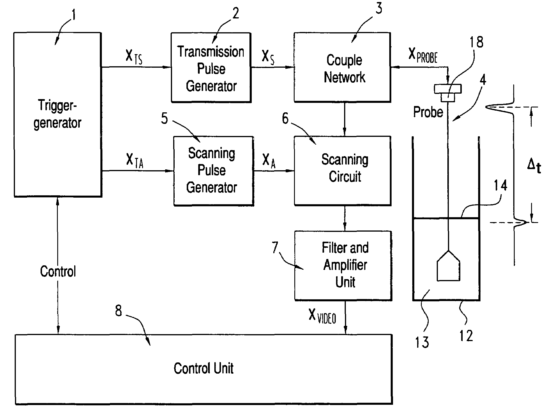
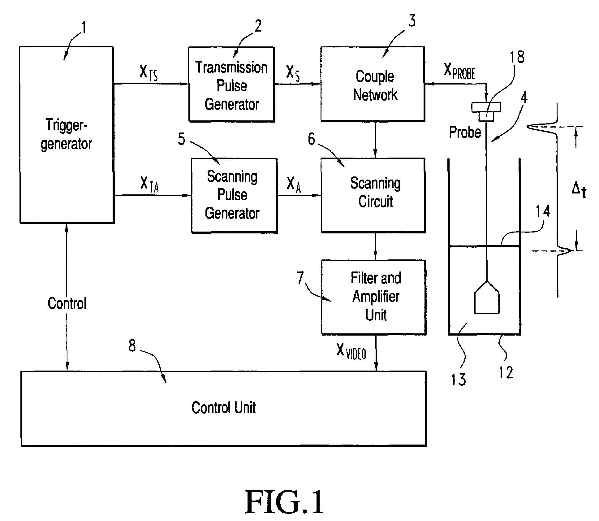
[0043]In FIG. 1, the basic layout of a tdr fill level sensor with improved security against interference is shown schematically, as an example of an application of the invention. The key part of the sensor is a waveguide 4, whose upper end forms the process terminal 18 and for instance is a retaining part 18; the waveguide 4 protrudes into a container 12 and dips partway into a medium 13 contained therein which forms a surface 14 and hence a boundary layer 14. A trigger generator 1 is used to generate a transmission trigger signal XTS at the pulse repetition frequency fprf and a scanning trigger signal XTA at the scanning frequency fA. The trigger generator 1 is controlled by a control unit 8. Examples of the detailed embodiment of the trigger generator 1 are shown in FIGS. 4–6 and explained in conjunction with them.

[0044]The transmission trigger signal XTS is supplied to a transmission pulse generator 2, which as a result is made to generate transmission pulses XS of a predetermine...


PUM


Abstract

The invention relates to methods and a circuit for increasing the interference resistance of a time frame reflectometer, in particular with respect to high frequency irradiation. A transmitted pulse (XS) is generated at a pulse repeater frequency (fprf) and coupled to a wave guide (4). A return signal (Xprobe) is returned to the wavwguide (4) by a reflector (14) which is connected to said waveguide (4) and is scanned for time-expanded representation as a reflection profile with scan pulses (XA) which are repeated at a scan frequency (fA) and measurement values are continuously calculated from said reflection profiles, expressing the distance from the reflector (14) to the process connection. The scanning frequency (fA) and the pulse repeater frequency (fprf) are altered and either the expanded time representation of the reflection profile remains unchanged or when a time change occurs in the reflection profile and said change in time expansion is and taken into account in evaluating the profile, whereby an interference factor is determined from at least one measurement of said reflection profile. In order to decide on the usability of the measurement values, an algorithm is used to calculate on the basis of the measured values said interference to the extent that sufficient measuring accuracy is attained. A circuit arrangement comprising a trigger generator (1) is used to implement the method.

Description

FIELD OF THE INVENTION[0001]The invention relates to a method for increasing the interference resistance of a time domain reflectometer, in particular to high-frequency radiation, in which at a pulse repetition frequency a transmission pulse is generated and coupled into a waveguide, whose upper end toward the process terminal is disposed on a holder part. The invention also relates to a circuit arrangement for performing the method.PRIOR ART[0002]For determining the fill level of media in a container, sensors based on time domain reflectometry (TDR) are known.[0003]U.S. Pat. No. 5,609,059 provides an overview. Such sensors are based on the transit time measurement of electromagnetic signals that are propagated along an open waveguide that protrudes into the medium. The waveguide is for instance a Sommerfeld line, a Goubau line, a coaxial cable, a microstrip, or a coaxial or parallel arrangement of two lines. At the boundary face to the outer medium, or in the case of layering insid...

Claims


Application Information

Patent Timeline
Patent Type & Authority Patents(United States)
IPC IPC(8): G01R27/04G01R31/11G01S13/08G01F23/284G01S7/292G01S13/88
CPCG01F23/284
Inventor CRAMER, STEFANHERTEL, MARKUSKRIEGER, BERND
Owner EHNDRESS KHAUZER GMBKH KO KG
Why Eureka
Try Eureka