Electrode for fuel cell, method of manufacturing same, and fuel cell with such electrode

Inactive Publication Date: 2006-08-15
HONDA MOTOR CO LTD
View PDF24 Cites 10 Cited by
  • Summary
  • Abstract
  • Description
  • Claims
  • Application Information

AI Technical Summary

Benefits of technology

[0027]In the electrode having the water-repellent layer, the water-repellent layer repels water. Therefore, even if a large amount of H2O is produced when the fuel cell is operated to generate electricity at a high current density, a liquid electrolyte is prevented from seeping from a composite electrolyte.
[0037]A slight amount of solvent may remain in the water-repellent layer thus formed. It is preferable to further heat the assembly for volatilizing away the remaining amount of solvent. The assembly is preferably heated in order to increase the water repellency of the water-repellent layer and the bonding strength between the water-repellent layer and the base.

Problems solved by technology

Specifically, when the fuel cell generates electricity at a large current density, the voltage across the fuel cell drops below a desired level, failing to sufficiently energize the load connected to the fuel cell.
However, the resulting fuel cell increases in weight and size, requiring a large installation space on the automobile.
The automobile with the fuel cell carried thereon also becomes heavy.
When the interstices of the gas diffusion layer 6b clogged, it is difficult for the supplied oxygen-containing gas to be diffused to the electrode catalyst layer 7b, making it difficult for the reaction represented by the formula (B) to take place.
However, the water-repellent layer thus produced tends to crack easily to the extent that the produced cracks usually reach about 5%, or about 15% at maximum, of the total area of the water-repellent layer.
An electrode catalyst layer somehow coated on the gas diffusion layer also tends to crack and suffer surface irregularities.
The crack in the electrode catalyst layer obstructs electric conduction in the electrode catalyst layer.
Consequently, it is highly difficult to construct a fuel cell which is capable of achieving a high output at a high current density.

Method used


Image

  • Electrode for fuel cell, method of manufacturing same, and fuel cell with such electrode
  • Electrode for fuel cell, method of manufacturing same, and fuel cell with such electrode
  • Electrode for fuel cell, method of manufacturing same, and fuel cell with such electrode

Examples


examples

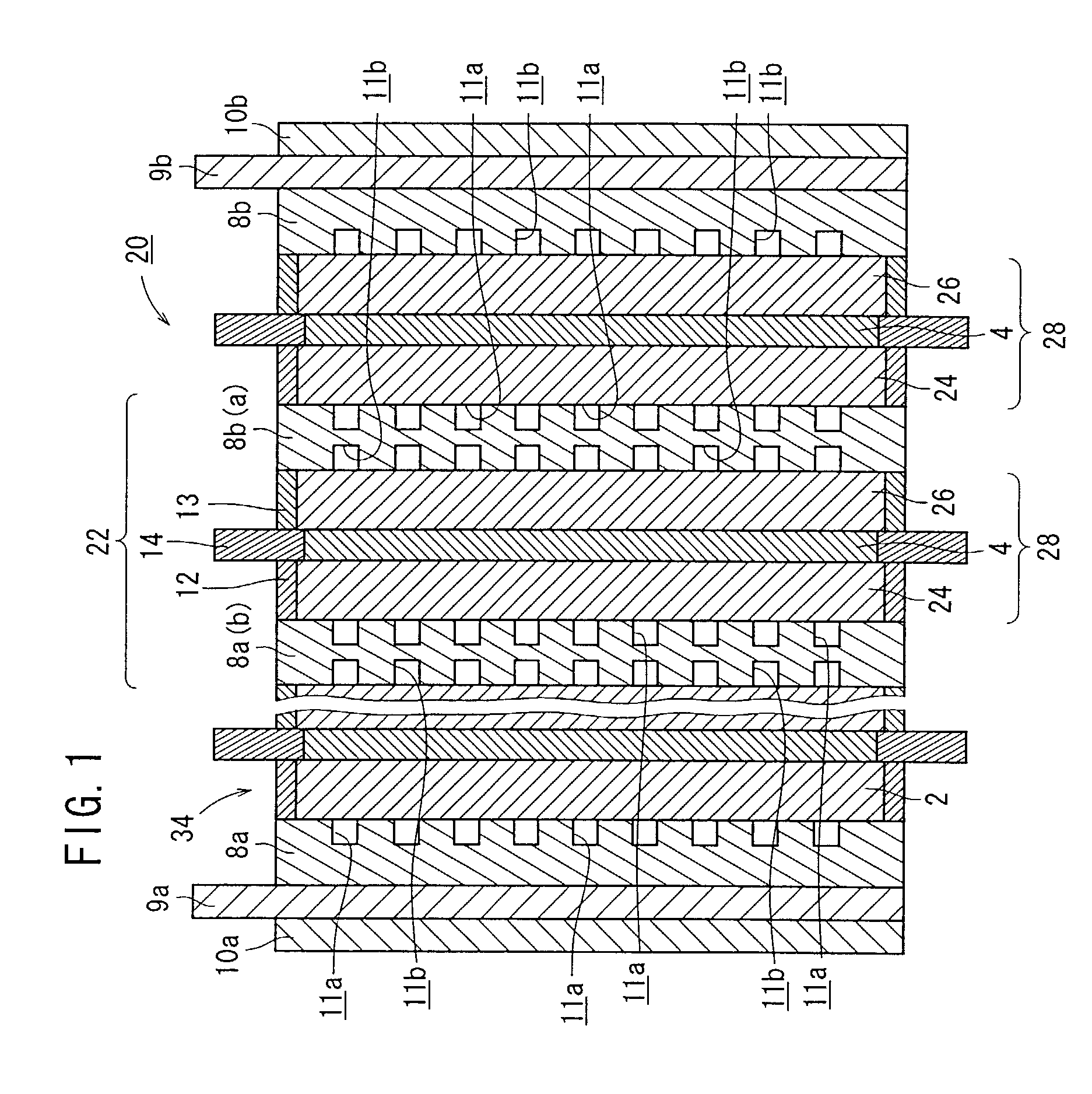
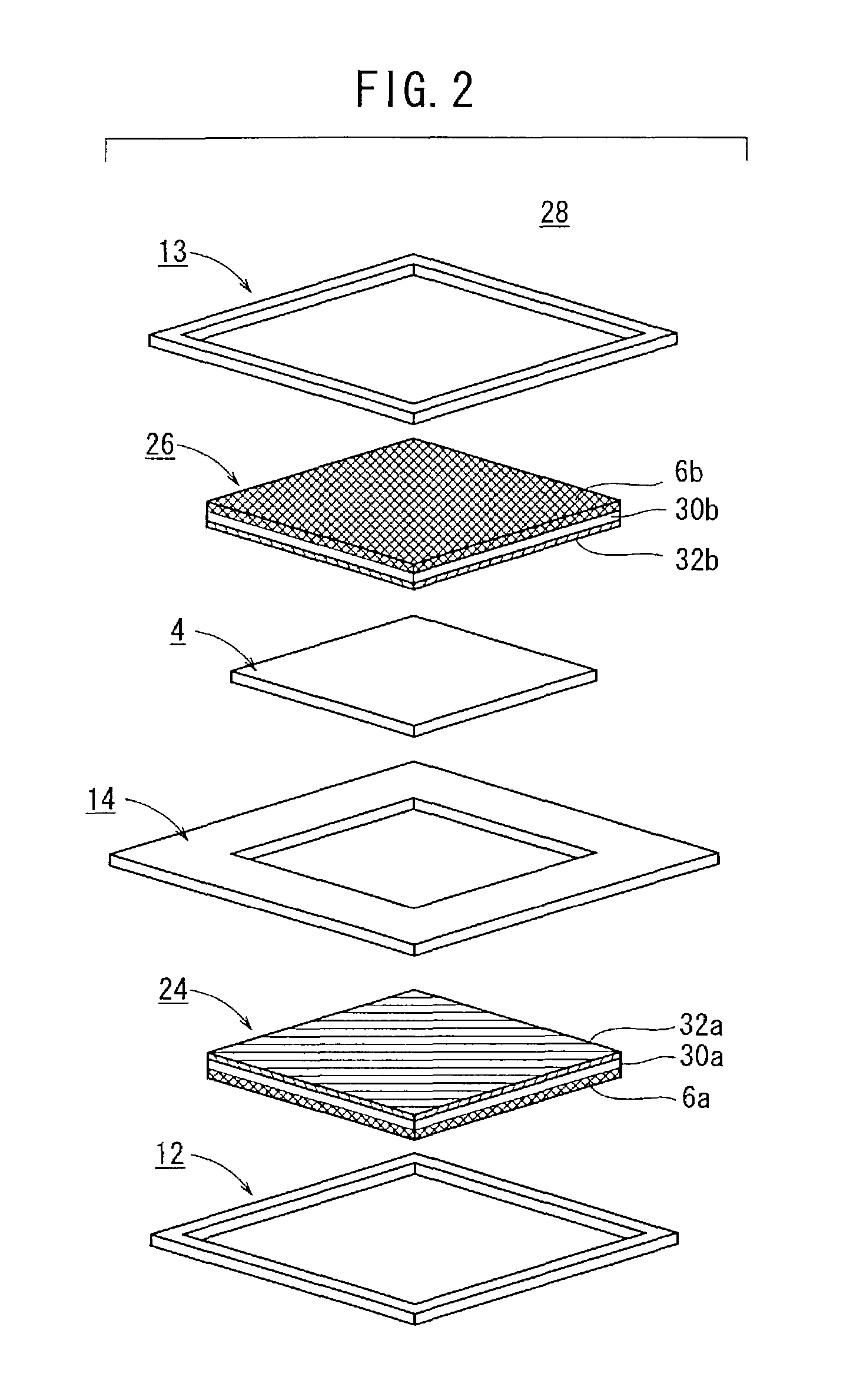
(1) Production of Fuel Cells 20:

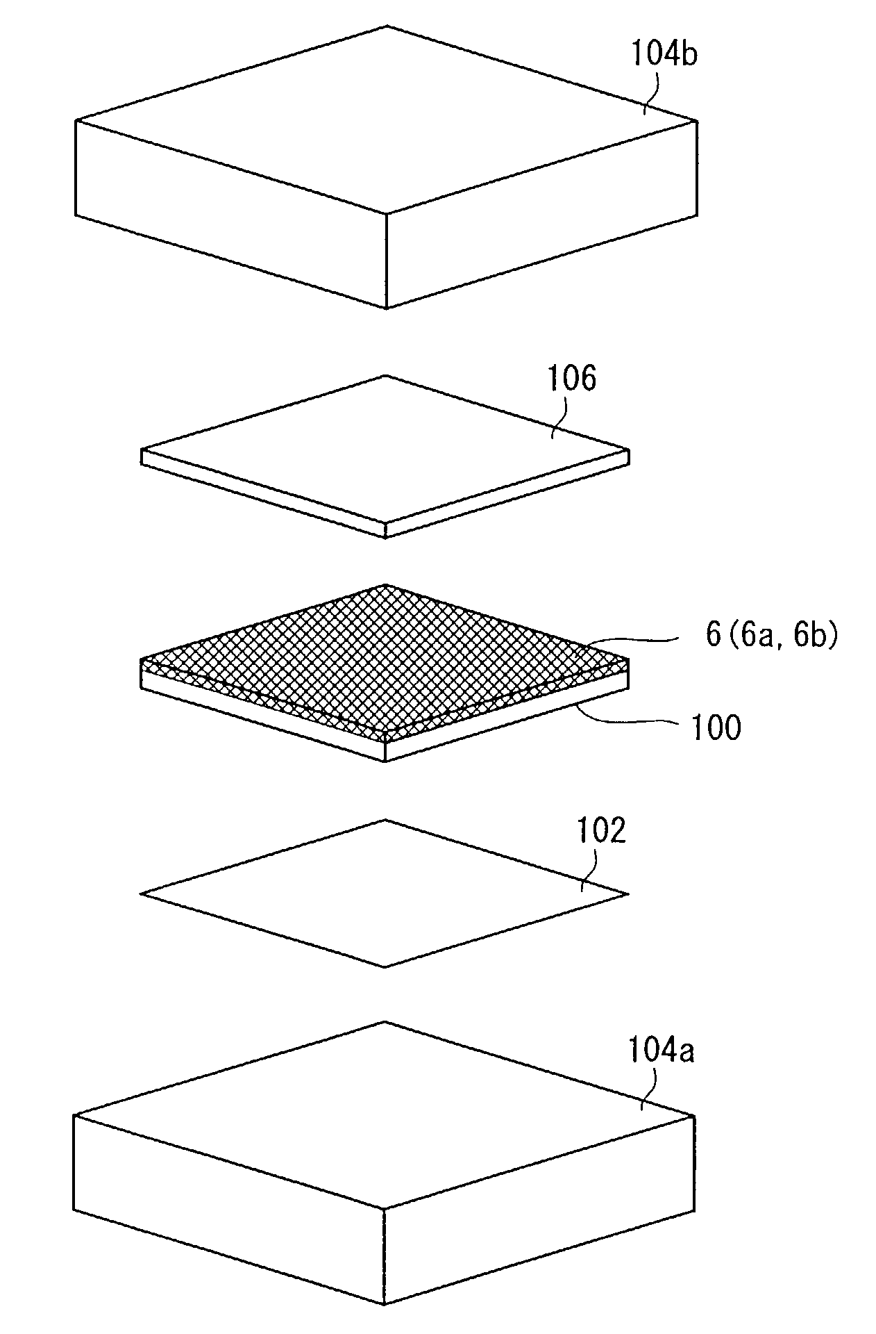
[0109]60.6 weight % of PTFE particles having a diameter ranging from 200 to 300 nm, 5 weight % of a surface active agent, and 34.4 weight % of pure water were mixed into a PTFE dispersion. 49.5 parts by weight of the PTFE dispersion, 70 parts by weight of carbon particles having a diameter ranging from 10 to 30 nm, and 840 parts by weight of a solvent of ethylene glycol (the boiling point is 197° C.) were mixed, by stirring, into a first paste 100.

[0110]The first paste 100 was coated on a sheet of carbon paper (manufactured by Toray) having a length of 60 mm, a width of 60 mm, and a thickness of 270 μm according to the screen printing process. Thereafter, the coated sheet was heated at 350° C. for 20 minutes to dry the first paste 100, producing a first layer composed of 0.9 mg of carbon particles and 0.39 mg of PTFE particles that were dispersed per 1 cm2 of carbon paper.

[0111]Then, the first layer was coated again with the first paste 100 according ...


PUM

PropertyMeasurementUnit
Fractionaaaaaaaaaa
Thicknessaaaaaaaaaa
Temperatureaaaaaaaaaa

Abstract

A fuel cell provides a high output at a high current density. The fuel cell has an anode electrode and a cathode electrode comprising a gas diffusion layer, a water-repellent layer disposed on the gas diffusion layer and containing a carbon material and polytetrafluoroethylene, and an electrode catalyst layer disposed on the water-repellent layer and containing a carbon material carrying a catalyst. The electrode catalyst layer has maximum and minimum thicknesses that differ from each other by less than 30 μm. The electrode catalyst layer has cracks whose area is less than 10% of a total area of the electrode catalyst layer.

Description

BACKGROUND OF THE INVENTION[0001]1. Field of the Invention[0002]The present invention relates to an electrode for a fuel cell which is capable of achieving a high output at a high current density, a method of manufacturing such an electrode, and a fuel cell having such an electrode.[0003]2. Description of the Related Art[0004]FIG. 9 of the accompanying drawings shows in vertical cross section a unit cell of a general phosphoric acid fuel cell which is one of presently available fuel cells. The unit cell, denoted at 1, has an electrolyte electrode assembly 5 which comprises an anode electrode 2, a cathode electrode 3, and an electrolyte 4 interposed between and joined to the electrodes 2, 3.[0005]The electrolyte 4 comprises a polymer membrane made of a basic polymer such as polybenzimidazole and impregnated with a liquid electrolyte. See U.S. Pat. No. 5,525,436 for details. The liquid electrolyte may, for example, be phosphoric acid, sulfuric acid, methanesulfonic acid, or the like w...

Claims


Application Information

Patent Timeline
IPC IPC(8): B01J21/18B05D5/12B29C65/00B32B37/00H01M4/86H01M4/88H01M4/96
CPCH01M4/8605H01M4/8807H01M4/8817H01M4/8882H01M4/96H01M4/8896Y02E60/50H01M2300/0005H01M2300/0008H01M2300/0011
Inventor IWASAKI, KAZUHIKOOHBA, TSUGIOMIYAMA, TAKESHIONODERA, MINAKO
Owner HONDA MOTOR CO LTD
Why Eureka
Try Eureka