
Panel performance testing system

a performance testing and panel technology, applied in the field of panel performance testing system, can solve the problems of needing to hang another cable, load was not transferred very smoothly to the cable, and use a motor-driven pulley, so as to improve the efficiency of testing, reduce equipment costs, and improve the accuracy and repeatability of test results.

Inactive Publication Date: 2006-08-15
HUBER ENGINEERED WOODS
View PDF20 Cites 11 Cited by
  • Summary
  • Abstract
  • Description
  • Claims
  • Application Information

AI Technical Summary

Benefits of technology

[0013]The loading head assembly is operable to impart a load to a first major face of a test panel between the retained opposite end portions of the panel. In one particular embodiment, the loading head assembly comprises two rectilinear contact rods for applying load to the first major face of a test panel along two parallel lines of contact made by the respective rods along their lengths with the first major panel face, particularly wherein the rods are spaced apart a distance of about one-third the total span of the panel from the retained end portions to provide a three-point bending system.
[0017]In one particular embodiment, the linear actuator comprises a roller screw and rolling elements operably connected to a rotary power transmission source and the output shaft. The linear actuator may comprise, for example, multiple threaded helical rollers assembled in a planetary arrangement around a portion of the output shaft comprising a threaded shaft, wherein the linear actuator converts rotary motion into linear movement of the threaded shaft. A constant power transmission source is provided to power the linear actuator (e.g., a D.C. servomotor, a D.C. stepper motor, and a constant torque A.C. motor). A motor controller, such as a processing card associated with an actuator motor, controls the rate of linear movement of the output shaft of the linear actuator. The linear actuator assembly has a position feedback assembly operable to generate signals corresponding to the position and velocity of the output shaft of the linear actuator. These signals are received and processed by the motor controller in real-time. The motor controller can maintain and, if needed, appropriately adjust the rate of output shaft movement via motor control, to ensure a constant rate of load transfer is maintained. The linear actuator assembly is mechanically coupled with the load-supporting platform such that it can lower the load-supporting platform during initial loading at a rate providing smooth transfer of weight from the platform to the load transfer assembly and hence the loading head. The linear actuator assembly is used to provide vertically movement (e.g., descent) of the platform at a controlled rate effective to load the cable component at a smooth, uniform rate with a progressively increasing amount of weight of the dead weight until the dead weight is fully suspended from the load transfer assembly, such as a cable component of a cable / pulley assembly, and no longer supported in any amount by the platform of the mobile loading platform assembly. In one particular embodiment, the motor controller is operable to control the rate of weight loading to a constant value between 0.005 to 5 inch per minute until the weight is fully suspended from the cable and unsupported by the platform. Among other contributed advantages, this inventive arrangement can eliminate testing error which may be associated with use of a hydraulic drive system for applying load in panel testing devices, which in turn provides more accurate and less variable results.
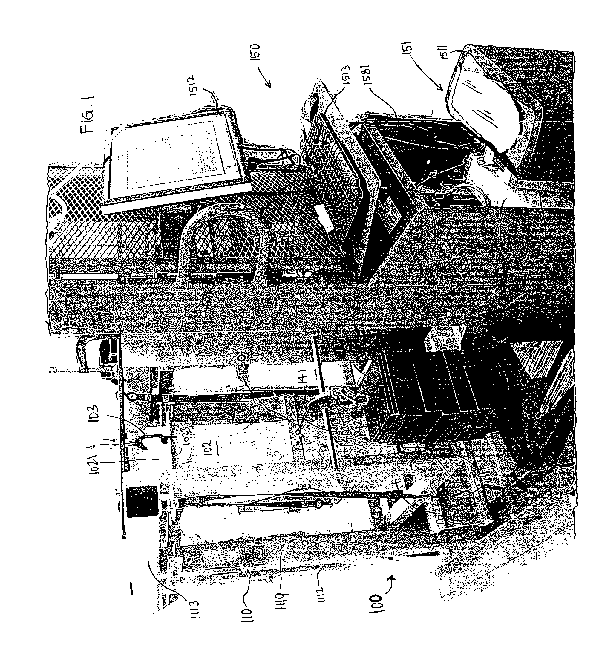
[0020]In one particular embodiment, the mobile loading platform assembly comprises a lift truck frame supporting the platform, the linear actuator, the computerized control system, and wheels for controlled movement of the lift truck frame towards and away from the test panel support frame. In this mobile configuration, the mobile loading platform assembly unit of the panel testing system only needs to be physically present at a given panel testing station for the initial loading stage of a panel creep test. Once loading to full stress load is achieved on a first test panel supported on a first test frame at a first test station using the mobile loading frame, the mobile loading frame can be redeployed for instituting initial loading of another test panel on another support frame at another test station. In this manner, the loading frame and its associated components need not be physically stationed at one given test station over the entire course of a load / deflection test period, such as a 90 day constant stress period of a creep test cycle, for each panel being tested. Instead, the mobile frame can be efficiently used to initially load a plurality of test panels supported on a plurality of associated test frames at different test stations at a testing facility.
[0022]In another embodiment, there is a method of implementing a panel performance testing system encompassing multiple panel testing stations by initially loading a plurality of different test panels supported on different respective test frames at different respective test stations located in the same test room by shuttling the same mobile platform assembly to successive different test stations after completing initial loading and while being absent during the constant stress portion of a creep test cycle as performed on a test panel at a previous test station. In this manner, the mobile platform assembly and associated components need not be dedicated to any given test station, and instead can be used to support a plurality of test stations at a given test facility, which improves testing efficiency and reduces equipment costs.
[0024]Additionally, the mobile loading platform assembly is a compact, maneuverable apparatus effective to help maximize the number of panel samples that can be loaded and concurrently tested at neighboring test stations in the minimal amount of space, since that space must be temperature and humidity controlled to conduct creep tests. The panel performance testing system also is conducive for comparative testing and problem solving. For instance, studies of the affects of varying a load rate and / or load amount on a given type of test panel can be efficiently implemented using the inventive panel testing system and methodology, such as by initially loading a plurality of different test panels supported on different test frames at different test stations located in the same test room in rapid succession by shuttling the same mobile loading platform assembly between each test station.

Problems solved by technology

The problem with this additive approach was that the load was not transferred very smoothly to the cable, or in other words, it was more of a step function loading.
The system using a motor-drive pulley had the disadvantage of the need to hang another cable to the weight stack, and having to unhook it from each weight stack before moving to the next specimen that needs to be loaded.
This added step might introduce some error to the data collection as well as take longer to apply load to many test panel samples.
An added disadvantage of the overhead pulley system is that it is larger and more cumbersome to maneuver in tight areas between rows of creep test frames.
As a result, engineering extrapolations often are not reliable, and the panel must be “over-engineered” to insure an adequate margin of performance capability.
Some panel bending tests, such as creep testing, may require load / deflection testing and data acquisition that lasts extended periods of time.

Method used


Image

  • Panel performance testing system
  • Panel performance testing system
  • Panel performance testing system

Examples


example

[0059]A lift truck including a lift frame and control panel space supported on rollers, WESCO Industrial Products, Model Number PSPL-60-2424-15S (Part No. 261074), capacity 1500 pounds, load center 15 inch, 24 inch×24 inch platform, was modified by removing the battery and the hydraulic motor and piston assembly. A hole was drilled in the lift platform to allow the bottom of a weight stack bolt to protrude through the platform deck. Three load cells (Omega Engineering LCHD-1K load cells) were installed in the deck and a steel plate was machined to fit onto the load cells, to allow the stack of weights to be supported by the steel plate and allowing the load cells to measure the weight of a stack of weights placed on the steel plate. A linear actuator / stepper motor (Electrak® 2000, Warner Electronic / Dana Corporation) with programmable motion control was installed in place of a hydraulic cylinder on the lift truck. The programmable motion control included a 3-Superior Electric SLO-SYN...


PUM

PropertyMeasurementUnit
lengthaaaaaaaaaa
widthaaaaaaaaaa
dead weightaaaaaaaaaa

Abstract

A panel performance testing system and method of use is provided for evaluating creep and duration of load (DOL) performance of products, particularly wood-based panels, subjected to bending stress. The panel performance testing system comprises a panel testing support frame assembly; a loading head assembly for applying test load to a panel face; a load transfer assembly for transferring load force from a dead weight to the loading head assembly; a panel deflection sensor; and a mobile loading platform assembly for vertically positioning and supporting dead weight loads, controlling the rate of load transfer of the dead weight loads from the loading platform assembly to the loading head assembly, and an integrated data acquisition system that automatically records and processes the related testing data for the entire course of the testing.

Description

FIELD OF THE INVENTION[0001]This invention relates to a system for testing time-dependent mechanical properties of visco-elastic materials such as panel or lumber products, and particularly a system for measuring the creep and duration of load (DOL) responses of the panels or lumbers under bending.BACKGROUND OF THE INVENTION[0002]An increasing demand exists for pre-fabricated structural panel materials, such as plywood, wafer board, oriented strand board, plaster board, composites of veneer and of wood-based layers, and so forth. These structural materials are heavily used, for instance, in the construction and manufacturing industries. Suppliers and users of these products often need to know their design values or capacities to assist them in making a proper material selection. For instance, among other tests, specimen or control panels cut from large panels or pulled from a given production lot or product type is tested to determine the major mechanical properties of the panel mat...

Claims


Application Information

Patent Timeline
Patent Type & Authority Patents(United States)
IPC IPC(8): G01N3/02
CPCG01N3/20G01N2203/0208G01N2203/0071
Inventor SCOVILLE, CHRISTOPHER R.PU, JIANHUA
Owner HUBER ENGINEERED WOODS
Learn More