
Advanced electrolytic polish (AEP) assisted metal wafer planarization method and apparatus

a technology of electrolytic polishing and metal wafers, applied in the direction of grinding/polishing apparatus, grinding machines, manufacturing tools, etc., can solve the problems of reducing the the non-planar outer surface presents a problem for the integrated circuit manufacturer, and the difficulty in achieving a high degree of surface uniformity or planarity. , to achieve the effect of reducing dishing and erosion, good quality and high throughpu

Inactive Publication Date: 2006-07-18
APPLIED MATERIALS INC
View PDF98 Cites 4 Cited by
  • Summary
  • Abstract
  • Description
  • Claims
  • Application Information

AI Technical Summary

Benefits of technology

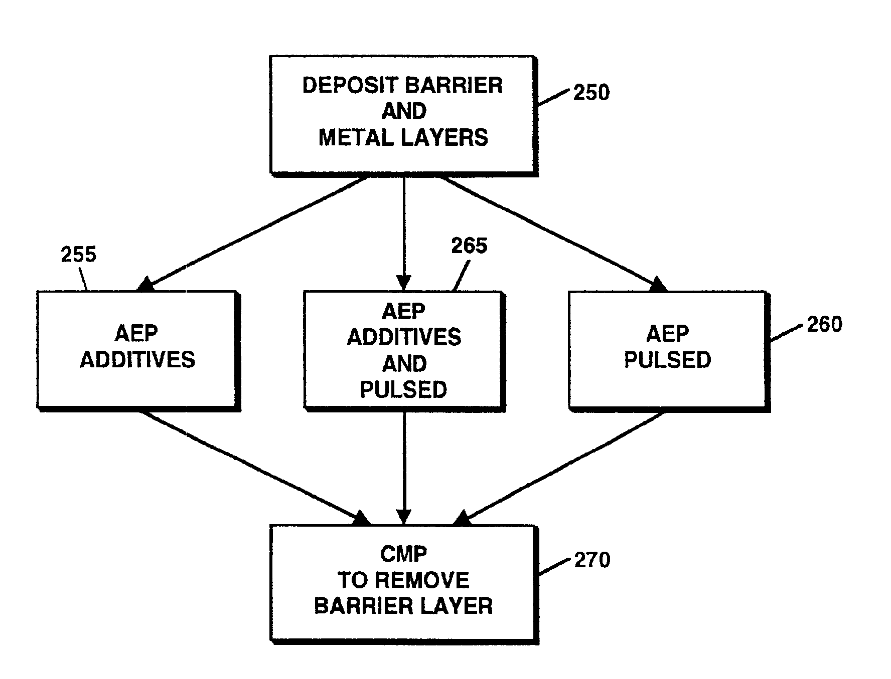
The present invention is an advanced electrolytic polish (AEP) assisted metal wafer planarization method and apparatus that solves the problem of reducing dishing and erosion while achieving planarized processed substrates. The AEP method uses a reverse electroplating method along with surface modifying methods, either alone or in combination, to remove material from a substrate in order to planarize the substrate. The polish stops precisely at a barrier layer, but alteration of the electrolyte chemistry would alter the depth and layers removed in the polish. The AEP method can be used as a first step, a second step, or a last step in the manufacture of all kinds of patterned metal wafers. The AEP technique provides a planarized surface without erosion and with very little dishing.

Problems solved by technology

This non-planar outer surface presents a problem for the integrated circuit manufacturer.
In applying conventional planarization techniques, such as CMP, it is extremely difficult to achieve a high degree of surface uniformity, particularly across a surface extending from a dense array of features, for example copper lines, bordered by an open field.
Copper or a copper alloy is then deposited, as by electroplating, electroless plating, physical vapor deposition (PVD) at a temperature of about 50° C. to about 150° C. or chemical vapor deposition (CVD) at a temperature under about 200° C., typically at a thickness of about 8000 Å to about 18,000 Å. In planarizing the wafer surface after copper metallization using CMP, undesirable erosion and dishing typically occur, decreasing the degree of surface uniformity or planarity and challenging the depth of focus limitations of conventional photolithographic techniques, particular with respect to achieving submicron dimensions, such as about 0.25 micron.
There are generally two causes for dishing formation: a) insufficient planarization and b) over-polish.

Method used


Image

  • Advanced electrolytic polish (AEP) assisted metal wafer planarization method and apparatus
  • Advanced electrolytic polish (AEP) assisted metal wafer planarization method and apparatus
  • Advanced electrolytic polish (AEP) assisted metal wafer planarization method and apparatus

Examples


Embodiment Construction

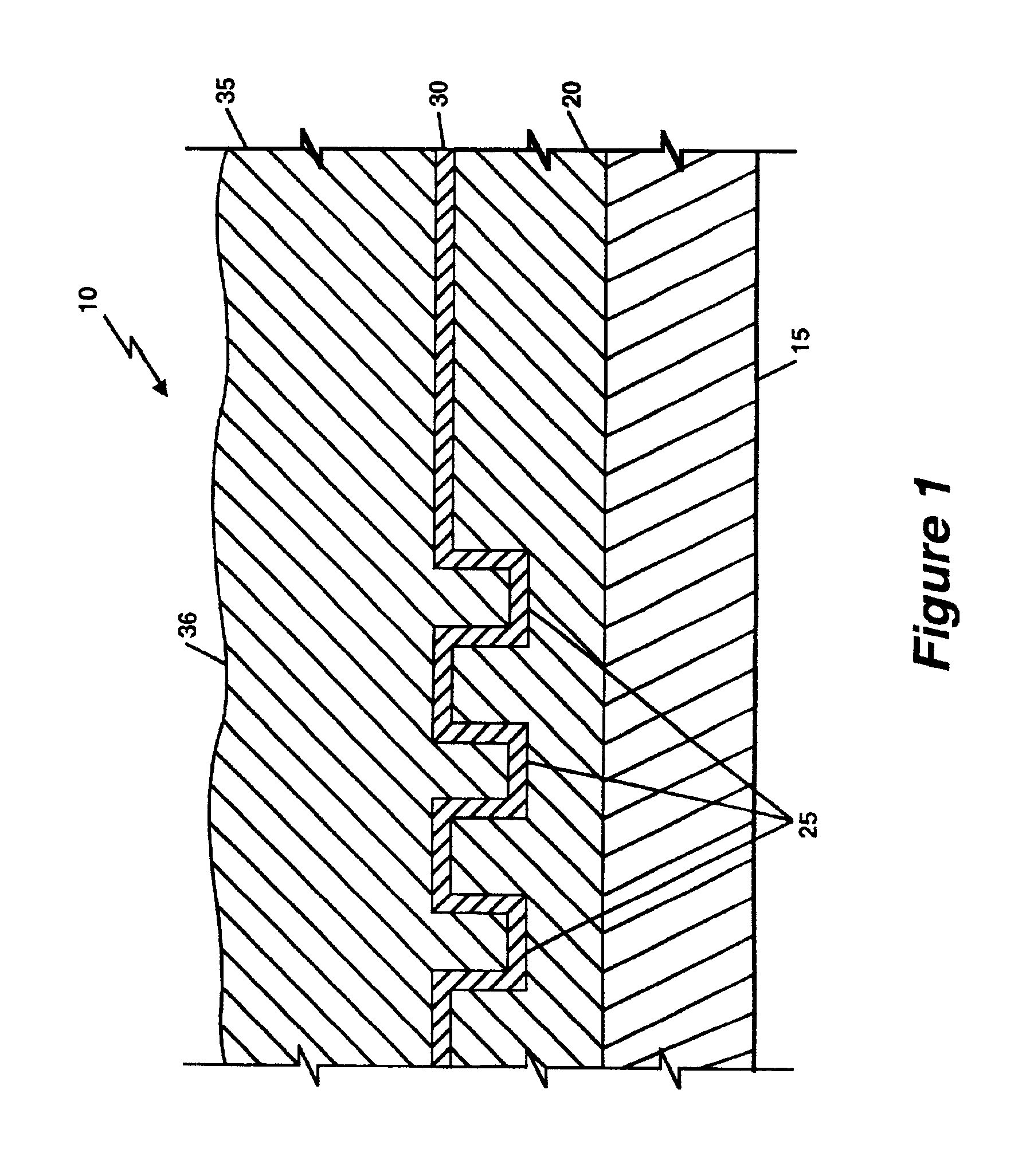
[0024]FIG. 1 shows a cross-sectional view of a conductive substrate 10 having deposited layers such as those layers formed during the manufacture of semiconductors. The figure is not to scale. An interlayer dielectric 20, e.g. silicon oxide, is formed overlying a metal wafer 15. A plurality of indentations, also referred to as openings 25, are formed in a designated area at the left of the interlayer dielectric 20 in which a dense array of conductive lines are to be formed bordering an open field shown on the right of the interlayer dielectric 20. A barrier layer 30, e.g. tantalum, tantalum nitride, titanium or titanium nitride, is deposited on the layer of interlayer dielectric 20, the barrier layer 30 also lining the plurality of openings 25. A conductive layer 35, e.g. copper, is then deposited over the barrier layer 30. The successive layers forms an uneven topography 36 over the substrate which requires planarization before further processing. Also, successive process steps req...


PUM

PropertyMeasurementUnit
current densityaaaaaaaaaa
temperatureaaaaaaaaaa

Abstract

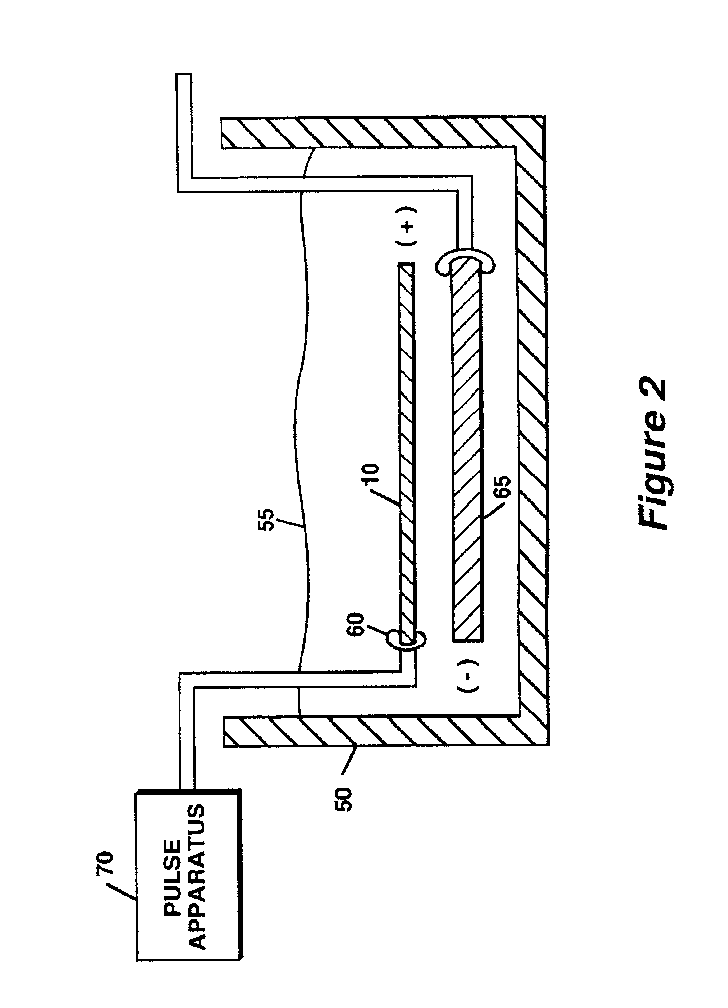
In advanced electrolytic polish (AEP) method, a metal wafer (10) acts as an anodic electrodes and another metal plate (65) is used as a cathodic electrode. A voltage differential is applied to the anode and cathode under a predetermined anodic dissolution current density. This causes a reaction that provides a planarized surface on the metal wafers. Additives are included in the electrolyte solution (55) which adsorb onto the wafer surface urging a higher removal rate at higher spots and a lower removal rate at lower spots. Also, in another embodiment of the present invention is a pulsed-electrolytic process (260) in which positive and negative potentials are applied to the anodic and cathodic electrodes alternately, further encouraging surface planarization. AEP can be used either as a first step followed by a mechanical polish or a second step between initial CMP polish and a third step mechanical polish. The present invention may also be added as a last step of copper electroplating process and so may be used in the manufacture of all kinds of patterned metal wafers.

Description

CROSS-REFERENCE TO RELATED APPLICATIONS[0001]This application is a divisional of U.S. utility application Ser. No. 09 / 450,858 , U.S. Pat. No. 6,299,741, entitled, “An Advanced Electrolytic Polish (AEP) Assisted Metal Wafer Planarization Method and Apparatus” filed Nov. 29, 1999 by the present applicants.FIELD OF THE INVENTION[0002]This invention relates generally to planarization of metal substrates and more particularly to advanced electrolytic polishing of metal films on semiconductor wafers.BACKGROUND OF THE INVENTION[0003]Integrated circuits are typically formed on substrates, particularly silicon wafers, by the sequential deposition of conductive, semiconductive or insulative layers. After a layer is deposited, the layer is etched to create circuitry features. As a series of layers are sequentially deposited and etched, the outer or uppermost surface of the substrate, i.e., the exposed surface of the substrate, becomes increasingly non-planar. This non-planar outer surface pres...

Claims


Application Information

Patent Timeline
Patent Type & Authority Patents(United States)
IPC IPC(8): B24B1/00B23H3/00B23H3/08H01L21/304H01L21/321
CPCH01L21/3212H01L21/32115
Inventor SUN, LIZHONGTSAI, STANREDEKER, FRITZ
Owner APPLIED MATERIALS INC
Learn More