
Display device with detachable heat-sink structure thereof

a display device and heat sink technology, applied in the direction of casings/cabinets/drawers, casings/cabinets/drawers, instruments, etc., can solve the problems of reducing affecting the work efficiency of the display device, so as to reduce the rework time of the display device and shorten the length

Active Publication Date: 2006-06-20
NYTELL SOFTWARE LLC
View PDF7 Cites 36 Cited by
  • Summary
  • Abstract
  • Description
  • Claims
  • Application Information

AI Technical Summary

Benefits of technology

[0010]Accordingly, the present invention is directed to a display device capable of reducing rework time of the display device and allows use of a flexible printed circuit board with a comparatively shorter length for electrically connecting the display panel and the driving chip.
[0011]The present invention is also directed to a detachable heat-sink structure suitable for a display device for implementing easy and efficient replacement or maintenance of the flexible printed circuit board by detaching the detachable heat-sink structure and the fixing plate.
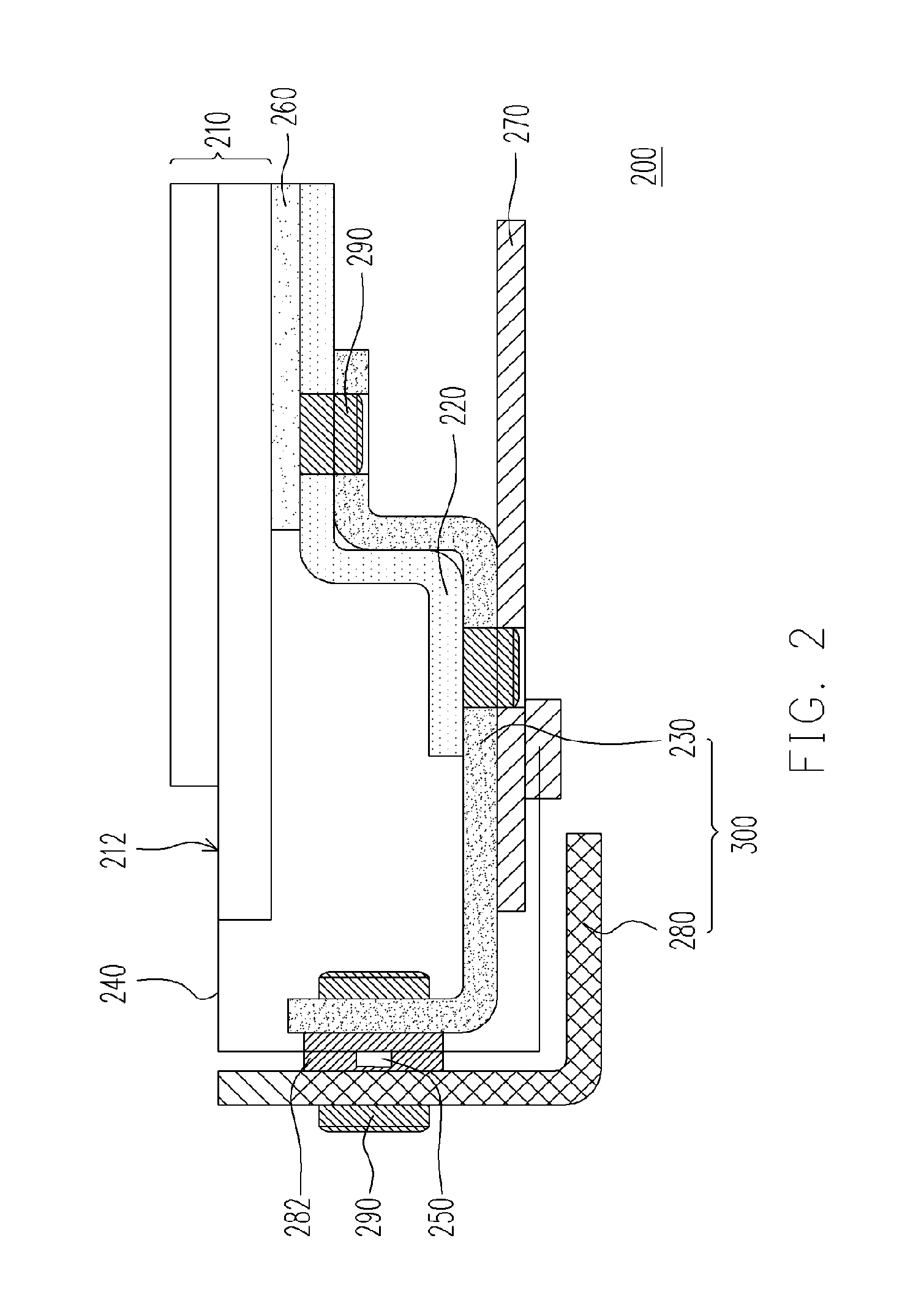
[0019]According to an embodiment of the present invention, because the heat-sink member and the fixing plate of the display panel are being detachably disposed, therefore the heat-sink member, the printed circuit board and the fixing plate can be easily detached for implementing rework or replacement of flexible printed circuit board in an abnormal event such as presence of undesirable objects in the electrodes of the peripheral circuit area 112 of the display panel 110 or the poor quality of the flexible printed circuit board 140. Particularly, because the peripheral circuit area of the display panel is remain exposed (that is, the peripheral circuit area of the display panel is not covered by the back plate), the rework of the flexible printed circuit board can be implemented without disassembling or separating the display panel and the back plate. Hence, the rework time of the flexible printed circuit board can be significantly reduced.

Problems solved by technology

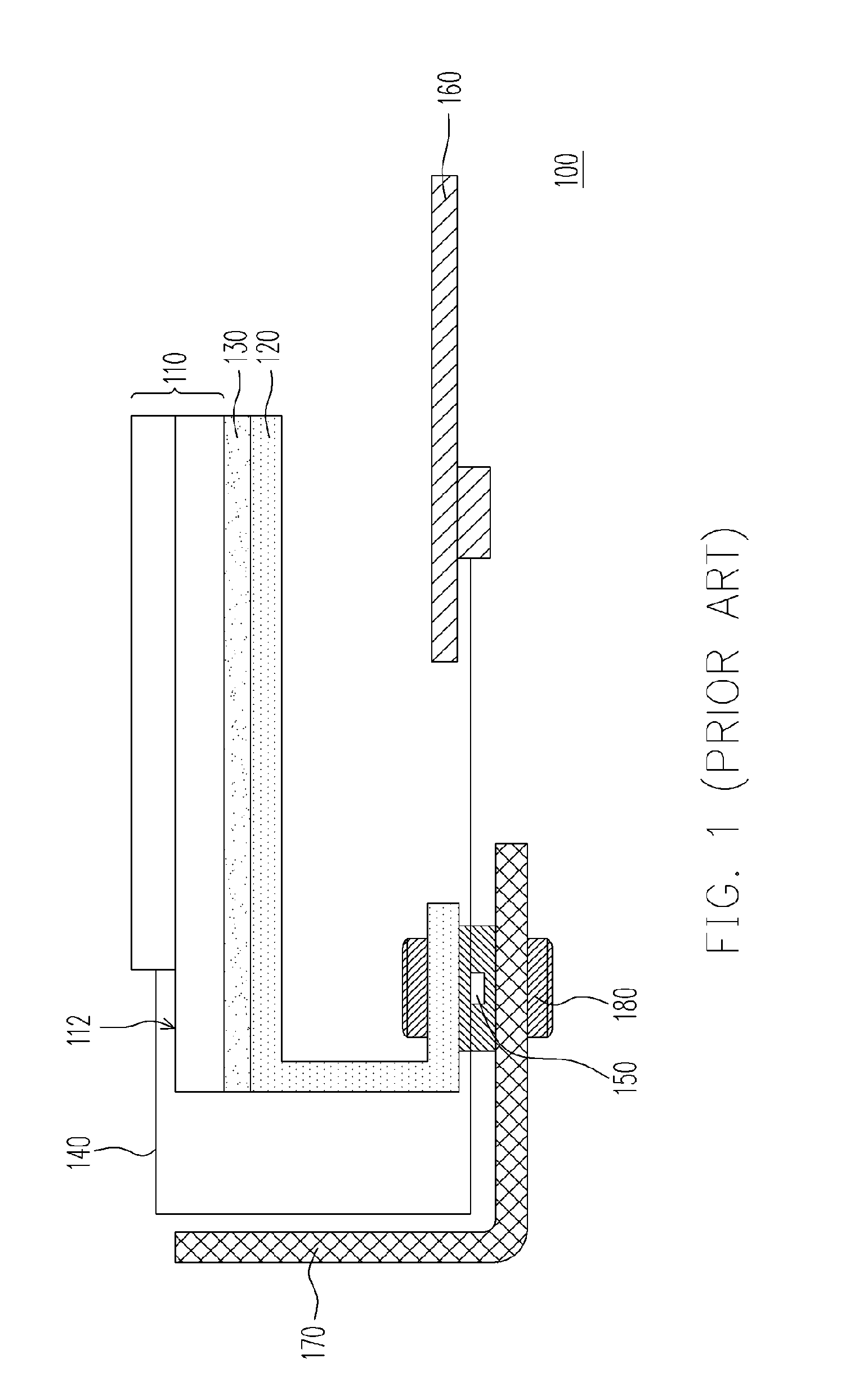
However, in an abnormal conditions, such as presence of undesired objects in the electrodes of the peripheral circuit area 112 of the display panel 110 or the poor quality of the flexible printed circuit board 140, the flexible printed circuit board 140 may get damaged during the thermal compression process for electrically connecting the flexible printed circuit board 140 and the peripheral circuit area 112 of the of the display panel 110 and as a result the flexible printed circuit board 140 may malfunction and may even result in breakdown of display device 100.
Accordingly, the rework of the display device 100 (i.e. changing the flexible printed circuit board 140) is complicated, incur wastage of the materials (i.e. cement, the chemical agent and etc), involve heavy labor work and consume substantial amount of time.
Therefore, the rework cost of the display device 100 is significant.

Method used


Image

  • Display device with detachable heat-sink structure thereof
  • Display device with detachable heat-sink structure thereof
  • Display device with detachable heat-sink structure thereof

Examples


Embodiment Construction

[0022]Various specific embodiments of the present invention are disclosed below, illustrating examples of various possible implementations of the concepts of the present invention. The following description is made for the purpose of illustrating the general principles of the invention and should not be taken in a limiting sense. The scope of the invention is best determined by reference to the appended claims.

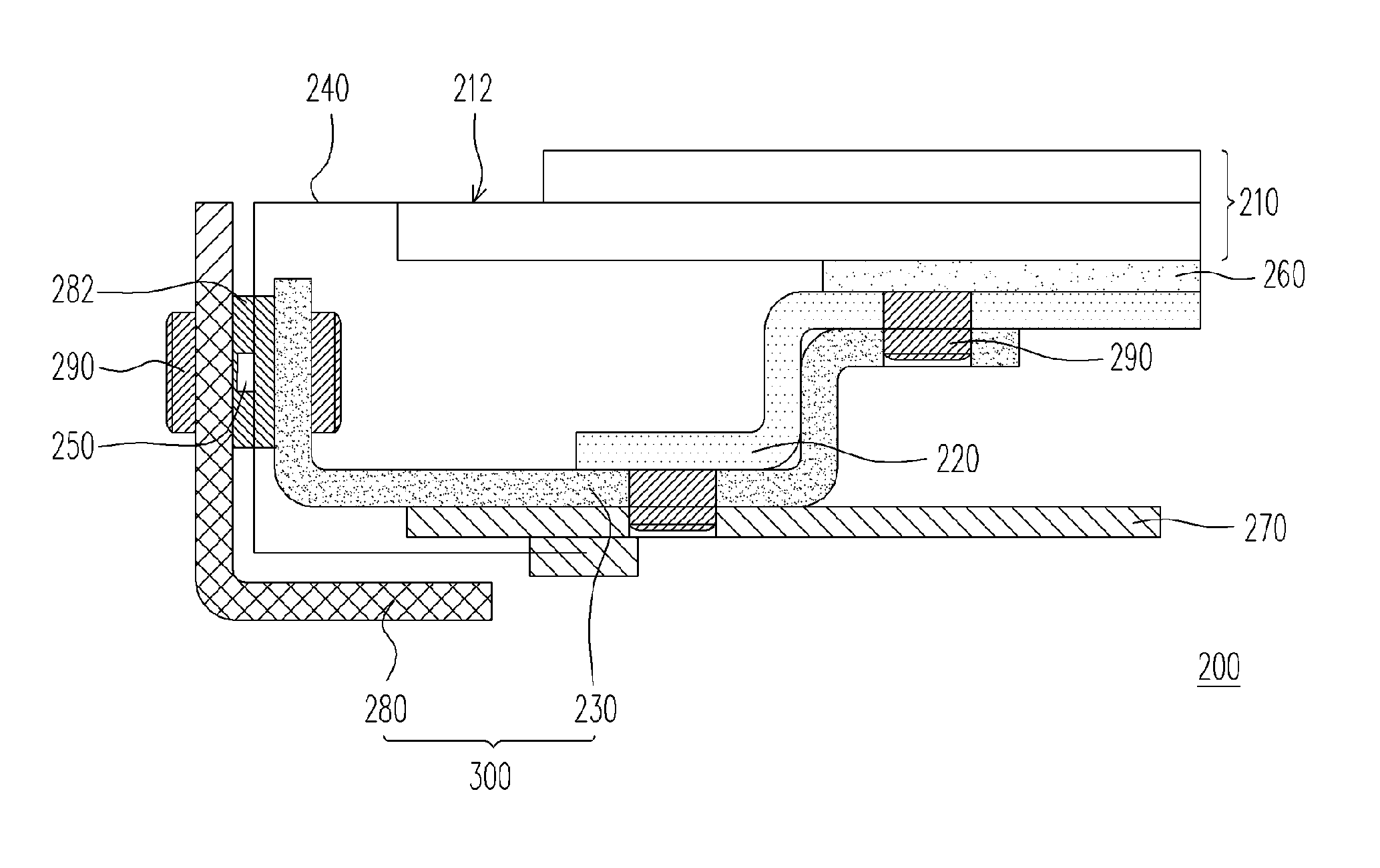
[0023]FIG. 2 is a schematic view of a display device according to one embodiment of the present invention. Referring to FIG. 2, the display device 200 is, for example, a plasma display panel (PDP) apparatus. The display device 200 mainly comprises a display panel 210, a back plate 220, a fixing plate 230, a flexible printed circuit board 240 and a driving chip 250. The display panel 210 has a peripheral circuit area 212. The back plate 220 is fixed on the display panel 210 and the peripheral circuit area 212 is extended outside the back plate 220 (i.e. the peripheral circuit a...


PUM

PropertyMeasurementUnit
areaaaaaaaaaaa
flexibleaaaaaaaaaa
thermally conductiveaaaaaaaaaa

Abstract

A display device comprises a display panel, a back plate, a fixing plate, a flexible printed circuit board and a driving chip. The display panel has a peripheral circuit area. The back plate is fixed on the display panel such that the peripheral circuit area remains exposed. The fixing plate is detachably installed on the back plate, and the flexible printed circuit board is disposed on the fixing plate, wherein the flexible printed circuit board is electrically connected with the peripheral circuit area. The driving chip is electrically connected with the flexible printed circuit board. Compared with the back plate, the driving chip is disposed adjacent to the peripheral circuit area. Because the peripheral circuit area of the display panel is exposed, the flexible printed circuit board can be directly reworked to shorten its rework time on the premise of no separation between the display panel and the back plate.

Description

BACKGROUND OF THE INVENTION[0001]1. Field of the Invention[0002]The present invention relates to a display device. More particularly, the present invention relates to a display device capable of reducing time of replacing the flexible printed circuit board (FPC) during rework of the display device.[0003]2. Description of Related Art[0004]Generally, the display device can be broadly classified into two types, namely cathode ray tube (CRT) display device and flat panel display device. As for the flat panel display device type, it can be further classified into several types such as liquid crystal display (LCD), plasma display panel (PDP), field emission display (FED) and the like.[0005]The working principle of plasma display panel (PDP) can be described as follows. A PDP typically comprises two glass substrates a plurality of electrodes and noble gas, for example, Ne, Xe, He, Xe etc. The electrodes are disposed on these two glass substrates respectively to form a plurality of discharg...

Claims


Application Information

Patent Timeline
Patent Type & Authority Patents(United States)
IPC IPC(8): H05K7/20G02F1/1333
CPCH05K7/20963H05K5/02
Inventor CHEN, SHENG-HSINFU, TSAO-YUAN
Owner NYTELL SOFTWARE LLC
Learn More