
Average controlled (AC) resonator driver

a technology of resonator driver and control circuit, which is applied in the field of electromechanical oscillators, can solve the problems of less well known, commercial costs, and less effective, and achieve the effect of low cos

Inactive Publication Date: 2006-06-13
DIALOG SEMICONDUCTOR GMBH
View PDF9 Cites 19 Cited by
  • Summary
  • Abstract
  • Description
  • Claims
  • Application Information

AI Technical Summary

Benefits of technology

"The present invention provides a circuit and method for generating stable oscillation signals with a precise duty-cycle of 50% at a low cost. The circuit can be made using low-cost integrated circuit technology and can be used with various types of resonators such as quartz or piezo crystals, or MEMS resonators. The circuit includes an oscillation generating circuit with a resonator and amplifying means, a voltage average controlling circuit, a control voltage generating circuit, a reference voltage producing circuit, and a voltage comparing and triggering circuit. The method involves inducing and sustaining controlled oscillations in the resonator and stabilizing the voltage average of the oscillation signal to a reference voltage. The circuit and method can be implemented in a monolithic integrated circuit and can reduce the cost of manufacturing and the dependence on resonator parameters and active components characteristics. The invention also provides a new method for generating a square wave clock signal with a precise duty-cycle of 50%."

Problems solved by technology

However, the dominant technology for the fabrication of most integrated circuits today is CMOS and design techniques for highly stable crystal oscillators in this technology are less well known, especially when it comes to frequencies of about 100 MHz, as necessary for modern communication applications.
Unfortunately, these approaches are somewhat expensive, both in terms of technical complexity (e.g. differential push-pull or balanced bridge structures, extra filter or tank circuits, sophisticated temperature compensation or gain control circuits, amplitude peak detectors etc.) and—hence—commercial costs.
The large chip areas needed and consequently the high costs are the main disadvantages of these prior art solutions.
It is therefore a challenge for the designer of such devices and circuits to achieve a high-quality but also low-cost solution.
This leads to large chip area or expensive process options and difficulties with respect to tuning by means of switched capacitor banks.
This results in a one pin oscillator.

Method used


Image

  • Average controlled (AC) resonator driver
  • Average controlled (AC) resonator driver
  • Average controlled (AC) resonator driver

Examples


Embodiment Construction

[0032]The following preferred embodiments disclose a novel oscillator circuit with an Average Controlled (AC) Resonator Driver.

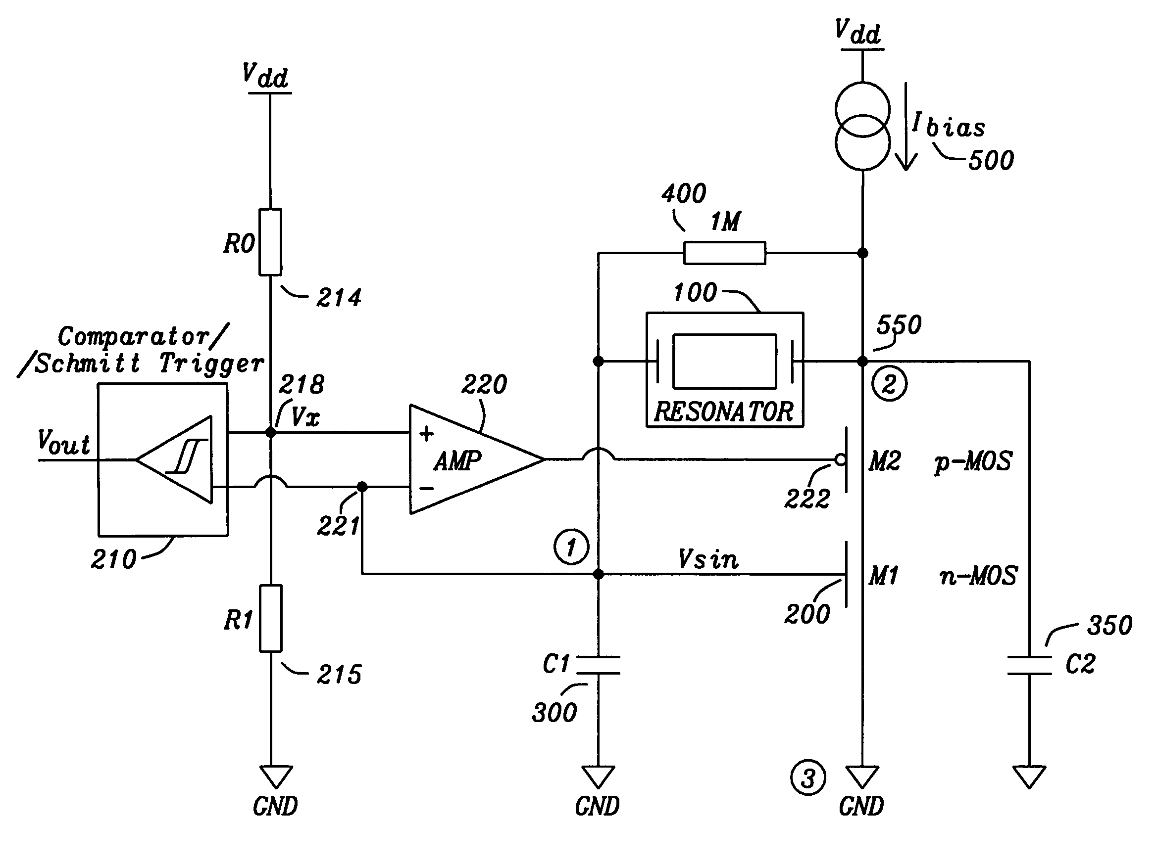
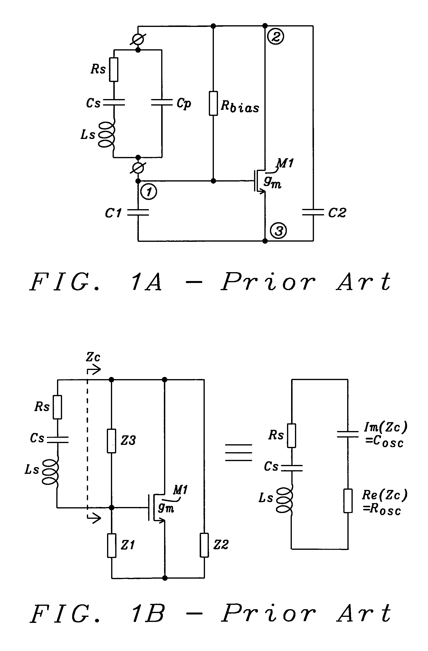
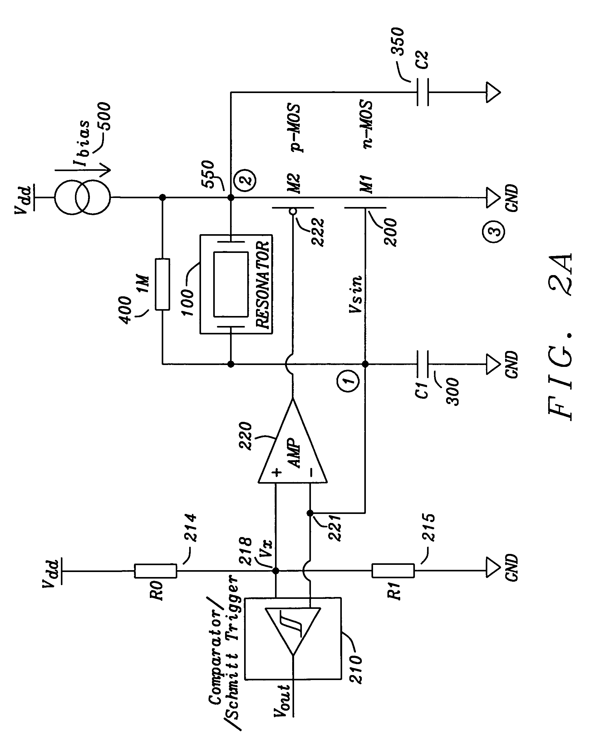
[0033]Contemplating now FIG. 2A, a circuit diagram of the new oscillator circuit with an Average Controlled (AC) Resonator Driver is given in form of circuit schematics for a first embodiment. The essential components from the basic three-point oscillator circuit as shown in FIG. 1A prior art can be relocated: between the supply voltage Vdd and ground (GND) a current source 500, named also as active supply component, delivering the bias-current Ibias leads to a central connection point 550, node 2 (comparable to node 2 (encircled) in FIG. 1A prior art), from there said newly introduced FET M2 (item 222) is connected in series with FET M1 (item 200), which itself is wired to ground. The additional FET M2 (item 222) is named also as Average Controlling (AC) component and enhancing the prior art circuit to said new AC Resonator Driver oscillator circuit. The re...


PUM


Abstract

Circuits and methods are given, to realize and implement an oscillator circuit with an Average Controlled (AC) Resonator Driver. A newly introduced additional Field Effect Transistor within a voltage average stabilizing regulation loop controlling the crystal oscillator's amplifier element produces an average voltage value stabilized sinusoidal oscillation signal which is then transformed into a square wave with a precise duty-cycle of exactly 50%. Said circuits and methods are designed in order to be implemented with a very economic number of components, capable to be realized with modern integrated circuit technologies.

Description

BACKGROUND OF THE INVENTION[0001](1) Field of the Invention[0002]The present invention relates generally to electronic oscillators usable as clock generators and in particular to improved crystal resonator oscillators, thin-film resonator or micro electromechanical resonator oscillators, realized with monolithic integrated-circuit technologies, where one chip solutions include automatic amplitude control and biasing to accommodate a highly accurate frequency-generation exhibiting low phase noise and stable amplitudes up to higher frequencies.[0003](2) Description of the Prior Art[0004]Crystal oscillators in monolithic integrated circuit technology are developed using Pierce oscillator or three-point oscillator circuit schemes, where the frequency determining resonator is working in a resonance mode, where the equivalent reactance is inductive. Realized with quartz crystals as resonators normally phase noise is considered sufficiently good at frequency offsets not too far away from t...

Claims


Application Information

Patent Timeline
Patent Type & Authority Patents(United States)
IPC IPC(8): H03L5/00H03B5/30H03B5/36
CPCH03K5/1565H03B5/364
Inventor ARIGLIANO, ANTONELLO
Owner DIALOG SEMICONDUCTOR GMBH
Learn More