
Catalyst structure and method of fischer-tropsch synthesis

a technology of catalyst structure and method, applied in the direction of catalyst activation/preparation, hydrocarbon preparation catalyst, metal/metal-oxide/metal-hydroxide catalyst, etc., can solve the problems of inability to improve conventional reactors, limited reaction rate, and hot spots in catalyst beds, etc., to achieve no increase in methane selectivity, short residence time, and high conversion rate

Inactive Publication Date: 2006-05-16
BATTELLE MEMORIAL INST
View PDF31 Cites 49 Cited by
  • Summary
  • Abstract
  • Description
  • Claims
  • Application Information

AI Technical Summary

Benefits of technology

[0016]It is another object of the present invention to provide a method of Fischer-Tropsch synthesis having shorter residence time.

Problems solved by technology

However, the overall reaction rate is severely limited by heat and mass transfer with conventional catalysts or catalyst structures.
The limited heat transfer together with the fast surface reaction kinetics may result in hot spots in a catalyst bed.
Because of the necessary operational parameters to avoid methanation, conventional reactors are not improved even with more active Fischer-Tropsch synthesis catalysts.
In addition, the experiment of reference 3 was done using a powdered catalyst on an experimental scale that would be impractical commercially because of the pressure drop penalty imposed by powdered catalyst.
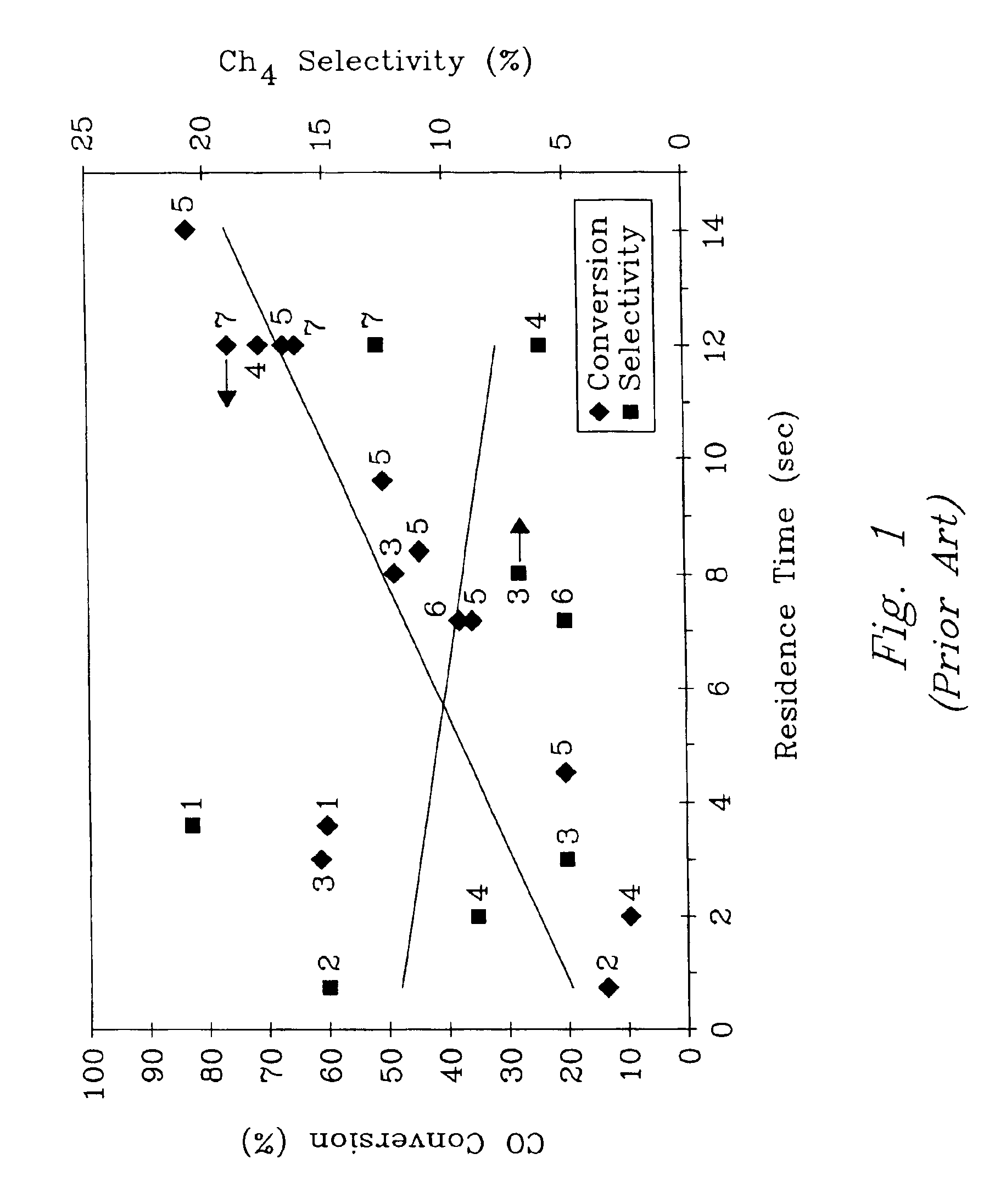
Operating at higher temperature will enhance the conversion, however at the much higher expense of selectivity to CH4.

Method used


Image

  • Catalyst structure and method of fischer-tropsch synthesis
  • Catalyst structure and method of fischer-tropsch synthesis
  • Catalyst structure and method of fischer-tropsch synthesis

Examples


example 1

[0036]A reactor was constructed with a reaction chamber with an inlet and an outlet. Internal reactor chamber dimensions were length 35.6 mm (1.4 in), height 1.5 mm (0.060 in) and width 8 mm (0.315 in).

[0037]Catalyst impregnated metal foam was made starting with a metal foam of stainless steel having a porosity of 90% as obtained from Astro Met, Cincinnati, Ohio. Foam metal surface was passivated and coated with a ceramic layer as described above.

[0038]15 wt % Co1 wt % Ru / γ-Al2O3 was synthesized in house using incipient wetness method. The powdered catalyst was ball-milled overnight and slurry dip-coated on foam metal until the desired loading was achieved. The coated catalyst was dried overnight and calcined at 350° C. for four hours.

[0039]In this experiment, two catalyst materials were used with exactly the same composition but in different physical form. Both catalyst materials had 15 wt % Co1 wt % Ru / γ-Al2O3. One was in powder form tested in a micro fixed-bed reactor according t...

example 2

[0042]An experiment was conducted to demonstrate operation at various pressures. The equipment was the same as in Example 1.

[0043]According to the literature, variation in pressure should only affect true residence time in Fischer-Tropsch synthesis. In other words, conventional wisdom in Fischer-Tropsch reactions is that reaction rate is proportional to pressure under identical gas hourly space velocity (GHSV).

[0044]However, as shown in Table E2-1, with the catalyst structure of the present invention, catalyst activity was unexpectedly enhanced as the pressure was decreased under the same temperature and pressure corrected residence time. This surprising result is attributed to the enhanced mass and heat transfer possible with the catalyst structure of the present invention.

[0045]

TABLE E2-1Engineered catalyst performance for Fischer-Tropsch synthesis at265° C. under a temperature and pressure correctedresidence time of 12.5 seconds.Pressure, atmConversion, %Selectivity to CH4, %5631...

example 3

[0046]Use of Co or Ru alone as a catalyst on the metal foam was also tested under the conditions of Example 1 and performance was confirmed worse than that of bimetallic catalyst such as Co—Ru.


PUM

PropertyMeasurementUnit
Temperatureaaaaaaaaaa

Abstract

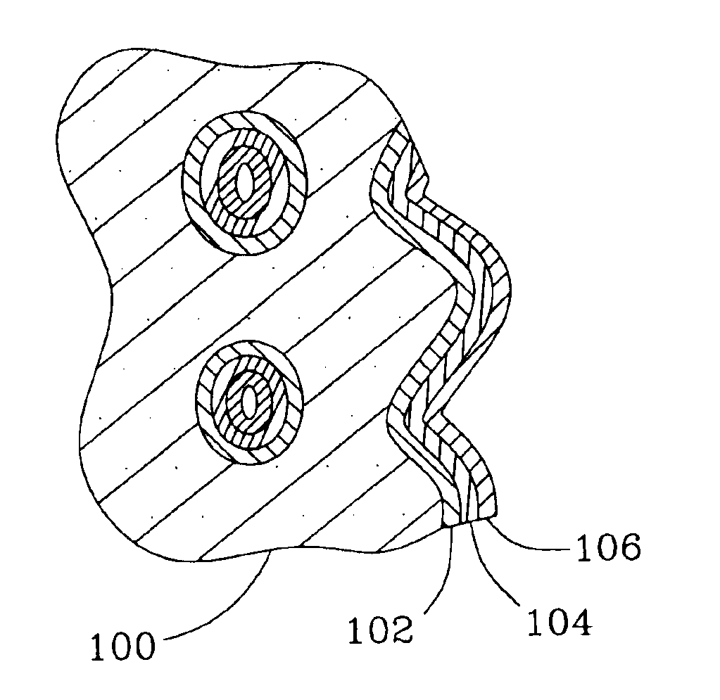
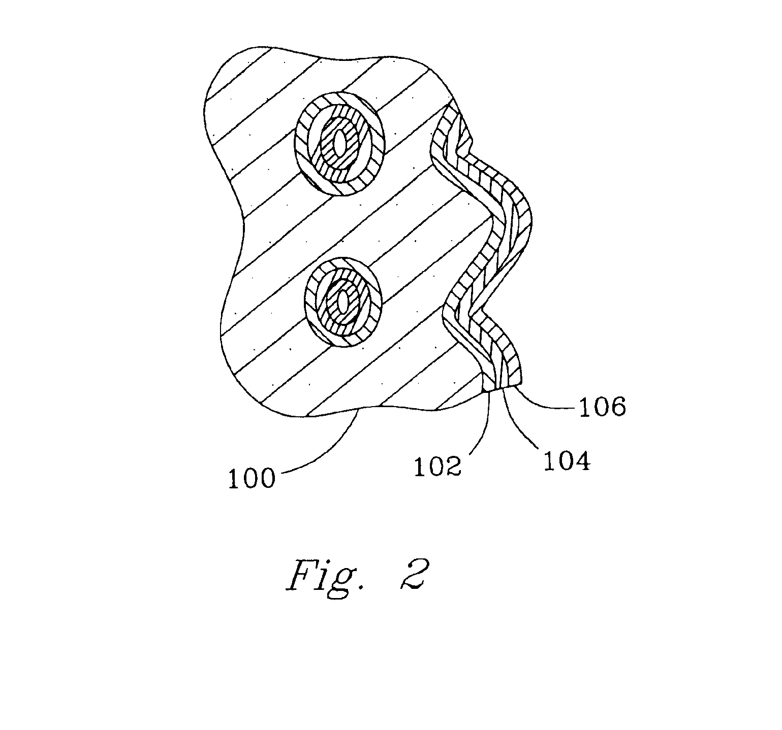
The present invention includes a catalyst structure and method of making the catalyst structure for Fischer-Tropsch synthesis that both rely upon the catalyst structure having a first porous structure with a first pore surface area and a first pore size of at least about 0.1 μm, preferably from about 10 μm to about 300 μm. A porous interfacial layer with a second pore surface area and a second pore size less than the first pore size is placed upon the first pore surface area. Finally, a Fischer-Tropsch catalyst selected from the group consisting of cobalt, ruthenium, iron and combinations thereof is placed upon the second pore surface area. Further improvement is achieved by using a microchannel reactor wherein the reaction chamber walls define a microchannel with the catalyst structure is placed therein through which pass reactants. The walls may separate the reaction chamber from at least one cooling chamber. The present invention also includes a method of Fischer-Tropsch synthesis.

Description

RELATED APPLICATIONS[0001]This is a divisional of Ser. No. 10 / 038,228, filed Jan. 3, 2002, now U.S. Pat. No. 6,660,237, which is a divisional of Ser. No. 09 / 375,610, filed Aug. 17, 1999, now U.S. Pat. No. 6,451,864, both of which are incorporated herein by reference as if reproduced in full below.FIELD OF THE INVENTION[0002]The present invention is a catalyst structure and method of making, and a method of Fischer-Tropsch synthesis.BACKGROUND OF THE INVENTION[0003]Fischer-Tropsch synthesis is carbon monoxide hydrogenation that is usually performed on a product stream from another reaction including but not limited to steam reforming (product stream H2 / CO ˜3), partial oxidation (product stream H2 / CO ˜2), autothermal reforming (product stream H2 / CO ˜2.5), CO2 reforming (H2 / CO ˜1) coal gassification (product stream H2 / CO ˜1) and combinations thereof.[0004]Fundamentally, Fischer-Tropsch synthesis has fast surface reaction kinetics. However, the overall reaction rate is severely limited ...

Claims


Application Information

Patent Timeline
IPC IPC(8): B01J21/04B01J23/00B01J23/02B01J29/06B01J8/02B01J12/00B01J19/24B01J23/89B01J35/00B01J35/02B01J35/10B01J37/02B01J37/025C07B61/00C07C1/04C07C9/02C07C9/04C07C9/15C10G2/00
CPCB01J8/0285C10G2/341B01J19/0093B01J19/248B01J19/249B01J19/2495B01J23/8913B01J35/0006B01J35/04B01J35/10B01J35/1076B01J37/0217B01J37/0225B01J37/0244B01J37/0248C07C1/041C07C1/0425C07C1/0455C10G2/32C10G2/33C10G2/332C10G2/34B01J12/007B01J37/0238B01J2219/00783B01J2219/00822B01J2219/00835B01J2219/00844B01J2219/0086B01J2219/00873B01J2219/00984B01J2219/2453B01J2219/2458B01J2219/2462B01J2219/32244B01J2219/32293B01J2219/32296B01J2219/32408B01J2219/32466B01J2219/32475C07C2523/46C07C2523/745C07C2523/75B01J35/19B01J35/56B01J35/60B01J35/657B01J23/462B01J23/75B01J37/0221B01J35/30B01J35/612
Inventor WANG, YONGVANDERWIEL, DAVID P.TONKOVICH, ANNA LEE Y.GAO, YUFEIBAKER, EDDIE G.
Owner BATTELLE MEMORIAL INST
Learn More