
Light-emitting device and method of fabricating the same

a technology of light-emitting devices and light-emitting surfaces, which is applied in the direction of semiconductor devices, basic electric elements, electrical apparatus, etc., can solve the problems of reducing the substantial amount of light extraction from the light extraction area, increasing the electrode area, and reducing the amount of light extraction. , to achieve the effect of effectively suppressing non-conformities, lowering the reflectivity of the reflective surface, and effectively suppressing non-conformities

Active Publication Date: 2006-05-09
SHIN-ETSU HANDOTAI CO LTD +1
View PDF7 Cites 19 Cited by
  • Summary
  • Abstract
  • Description
  • Claims
  • Application Information

AI Technical Summary

Benefits of technology

[0022]further comprising a contact layer for reducing junction resistance of the substrate-bonding conductive oxide layer, disposed between the light-emitting layer portion and the substrate-bonding conductive oxide layer so as to contact with the substrate-bonding conductive oxide layer.
[0160]For the case where the Si substrate is used for the device substrate, it is allowable to form the substrate-side bonding metal layer on the bonding-side main surface of the Si substrate, to form the second Au-base layer so as to cover the substrate-side bonding metal layer, and to anneal the substrate-side bonding metal layer and the Si substrate for alloying. When the n-type Si substrate is used, the substrate-side bonding metal layer can preferably be composed of an AuSb alloy or AuSn alloy. In this case, the effect of reducing the contact resistance can be raised by allowing the annealing for alloying the substrate-side bonding metal layer and the Si substrate to proceed typically within a temperature range from 100° C. to 500° C.

Problems solved by technology

Although some conventional efforts have been directed to increase the amount of light extraction by effectively spreading the current throughout the device through improving shape of the electrode, increase in the electrode area is inevitable in anyway, and this causes a dilemma that the amount of light extraction is restricted instead by decrease in the narrowing of the light extraction area.
This undesirably results in concentration of current density to the electrode-formed portion, and reduction in the substantial amount of light extraction from the light extraction area.
The conductive oxide layer such as being composed of ITO is, however, shows a large contact resistance with the compound semiconductor composing the light-emitting layer portion or the transparent conductive substrate, and the above-described direct bonding raises a problem in that the device will no more be operable at an appropriate operational voltage due to an excessively large forward series resistance.
Another disadvantage resides in that the conductive oxide layer in the above publication is formed by coating and baking of a colloidal solution containing ITO fine particles, where the conductive oxide layer formed by this method only shows a small bonding strength with respect to the transparent conductive substrate, and likely to cause separation.
Such DBR can be formed by hetero epitaxial growth of a thin compound semiconductor layer on the substrate prior to formation of the light-emitting layer portion, but the largeness in the number of layers to be grown tends to raise the cost.
It is also disadvantageous that the DBR, making use of difference in the refractive indices of the stacked semiconductor layers, can reflect the light incident at only a limited range of angle, so that a large increase in the light extraction efficiency is not expectable in principle.
The current-spreading layer in this method, formed in the early stage of the growth on the light-emitting-layer-growing substrate, must however satisfy a strict lattice matching condition as a consequence, and is restricted by various aspects.
AlGaAs has, however, only a relatively small band gap energy, and is likely to cause light absorption (in particular at a yellowish green emission wavelength around 560 nm).
It is also disadvantageous that Al contained therein is very likely to be oxidized at high temperatures during epitaxial growth of the light-emitting layer formed thereafter.
It is also disadvantageous that the epitaxial growth of the AlGaAs layer inevitably increases the number of process steps using expensive MOVPE process.
A large disadvantage resides in that a considerably thick current-spreading layer will be necessary to obtain a sufficiently large current spreading effect.
Still another disadvantage resides in that the current spreading layer has a considerably large dopant concentration, and this is causative of quality degradation of the light-emitting layer portion epitaxially grown thereon, diffusion of the dopant from the current-spreading layer to the light-emitting layer portion, and auto-doping.
AlGaInP alloy composing the light-emitting layer portion has, however, a larger band gap energy than GaAs has, and this raises a problem that the emitted light is absorbed by the GaAs substrate so as to make it difficult to attain a sufficient light extraction efficiency.
A large improvement in the light extraction efficiency is, however, not expectable in principle, because this type of reflective layer, making use of difference in the refractive indices of the stacked semiconductor layers, can reflect the light incident at only a limited range of angle.
A problem may, however, arise in that the area where the alloying proceeded to a certain degree considerably lowers the reflectivity, so that an effect of raising the light extraction efficiency through reflection on the metal layer is not always ensured to a satisfactory degree.

Method used


Image

  • Light-emitting device and method of fabricating the same
  • Light-emitting device and method of fabricating the same
  • Light-emitting device and method of fabricating the same

Examples


Embodiment Construction

(First Invention)

[0201]The following paragraphs will describe embodiments of the first invention referring to the attached drawings.

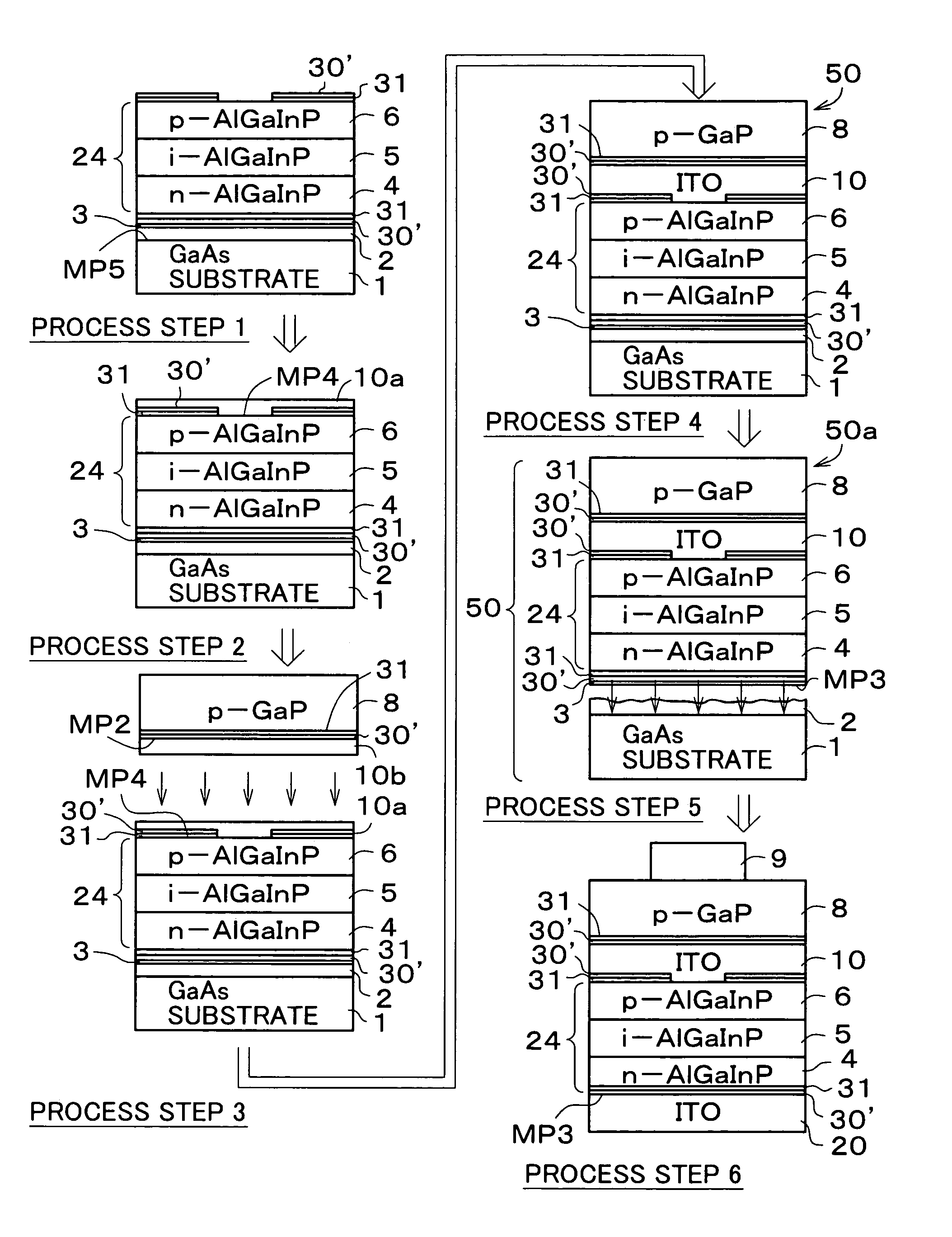
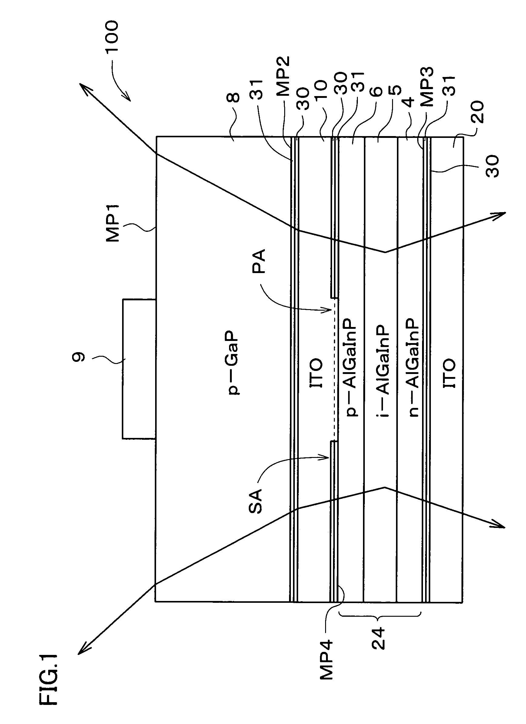
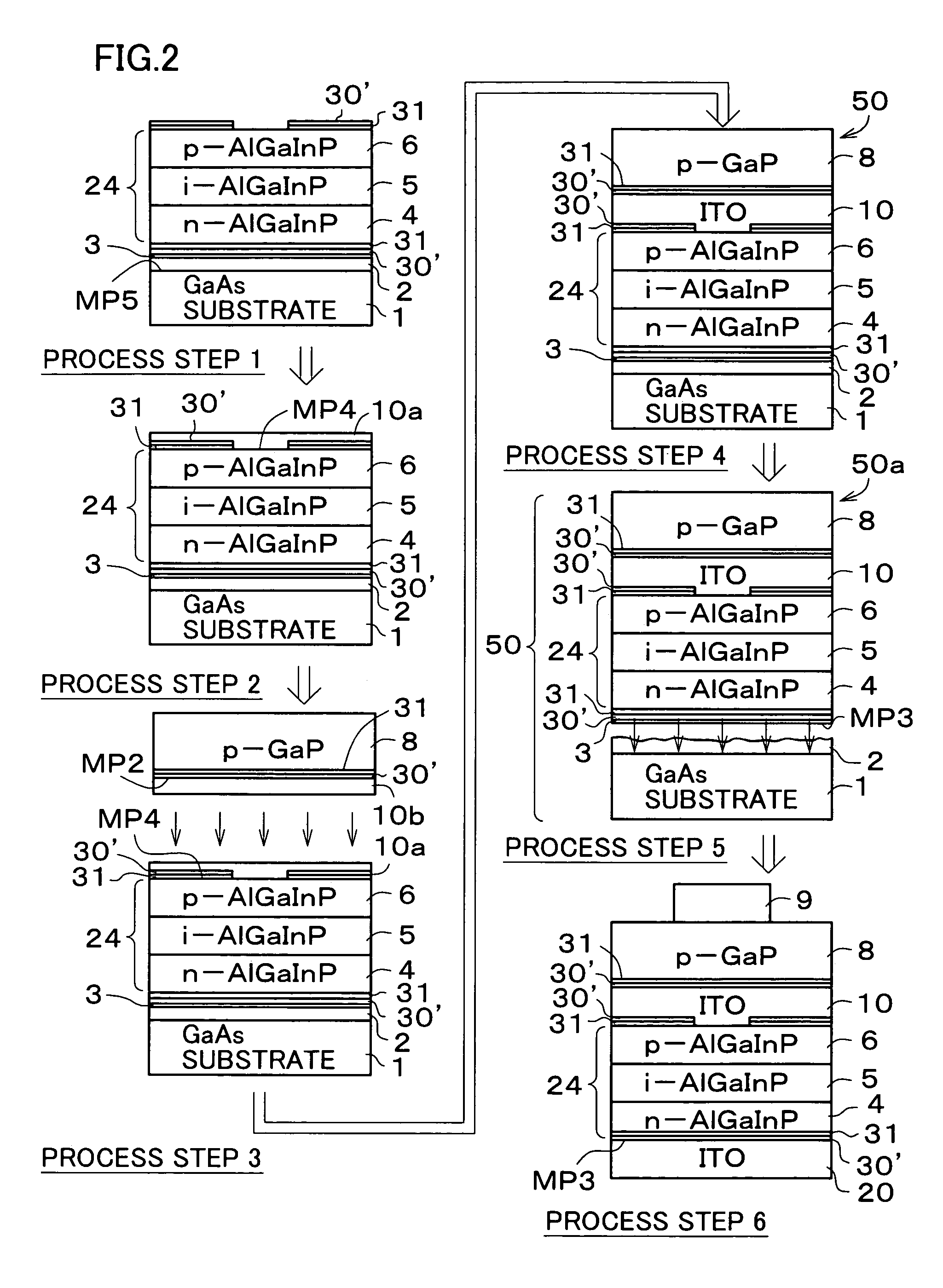
[0202]FIG. 1 is a conceptual drawing of a light-emitting device 100 of one embodiment according to the first invention. The light-emitting device 100 comprises a p-GaP single crystal substrate 8 as the transparent conductive semiconductor substrate, and a light-emitting layer portion 24 disposed on the main back surface MP2 thereof. The entire portion of the main back surface MP3 of the light-emitting layer portion 24 is covered with an ITO layer 20. The p-GaP single crystal substrate 8 functions as a current-spreading layer and a light extraction layer, and at around the center of the main surface MP1 thereof, a metal electrode (e.g., Au electrode) 9 for applying emission drive voltage to the light-emitting layer portion 24 is formed so as to cover a portion of the main surface MP1. The area around the metal electrode 9 on the main surface MP1 of the p...


PUM

PropertyMeasurementUnit
thicknessaaaaaaaaaa
thicknessaaaaaaaaaa
resistivityaaaaaaaaaa

Abstract

In a light-emitting device, a light-emitting layer portion composed of a compound semiconductor is bonded on one main surface of a transparent conductive semiconductor substrate while placing a substrate-bonding conductive oxide layer composed of a conductive oxide in between. Between the light-emitting layer portion and the substrate-bonding conductive oxide layer, a contact layer for reducing junction resistance with the substrate-bonding conductive oxide layer so as to contact with the substrate-bonding conductive oxide layer. This is successful in providing the light-emitting device which is producible at low costs, has a low series resistance, and can attain a sufficient emission efficiency despite it has a thick current-spreading layer.

Description

RELATED APPLICATION[0001]This application claims the priorities of Japanese Patent Applications No. 2002-308956 filed on Oct. 23, 2002, No. 2002-308970 filed on Oct. 23, 2002, No. 2002-308989 filed on Oct. 23, 2002 and No. 2003-023480 filed on Jan. 31, 2003.BACKGROUND OF THE INVENTION[0002]1. Field of the Invention[0003]The present invention relates to a light-emitting device and a method of fabricating the same.[0004]2. Description of the Related Art(First Invention)[0005]A light-emitting device having the light emitting layer portion composed of (AlxGa1−x)yIn1−yP (where, 0≦x≦1, 0≦y≦1; also referred to as AlGaInP, hereinafter) alloy can be realized as a high-luminance device by adopting a double heterostructure in which a thin AlGaInP active layer is sandwiched by an n-type AlGaInP cladding layer and a p-type AlGaInP cladding layer, both of which having a band gap energy larger than that of the active layer. Recent efforts have also succeeded in realizing a blue light-emitting devi...

Claims


Application Information

Patent Timeline
Patent Type & Authority Patents(United States)
IPC IPC(8): H01L21/00H01L21/30H01L33/00H01L33/10H01L33/14H01L33/38H01L33/40H01L33/42
CPCH01L33/0079H01L33/42H01L33/10H01L33/145H01L2933/0016H01L33/405H01L33/387H01L33/0093
Inventor YAMADA, MASATOISHIZAKI, JUN-YANOTO, NOBUHIKOHAGIMOTO, KAZUNORINOZAKI, SHINJIUCHIDA, KAZUOMORISAKI, HIROSHI
Owner SHIN-ETSU HANDOTAI CO LTD
Learn More