Semiconductor laser apparatus

a laser and semiconductor technology, applied in the direction of semiconductor laser arrangement, semiconductor laser, optical resonator shape and construction, etc., can solve the problems of limited wavelength range, response speed, and further complicated control circuits, and achieve stable longitudinal-mode operation, suppress longitudinal-mode hopping, and excel wavelength stability

Inactive Publication Date: 2005-11-22
HITACHI LTD
View PDF2 Cites 0 Cited by
  • Summary
  • Abstract
  • Description
  • Claims
  • Application Information

AI Technical Summary

Benefits of technology

[0009]The present invention provides a tunable laser capable of operating in a wide tunable wavelength range with a simple-structure control circuit and excels in wavelength stability, and a method for manufacturing the same. More particularly, the present invention provides a tunable laser that suppresses the longitudinal-mode hopping when being tuned and realizes a stable longitudinal-mode operation, and a method for controlling the wavelength of the tunable laser. Further, the present invention provides a tunable laser having an improved optical output through the improvement of a waveguide structure of a short-resonator laser that is effective to implement the above-mentioned operation. Moreover, the present invention provides an optical module that incorporates any of the above-mentioned optical devices and is capable of high-performance operation.
[0010]The laser of the present invention is tuned continuously with a single electric s

Problems solved by technology

Moreover, similar improved distributed reflection type lasers each of which uses a sample diffraction grating structure, or a super-structure diffraction grating structure, or the like in the diffraction grating part require further complicated control circuits.
However, the laser has intrinsic problems which require improvement in that laser channels must be switched over every time the emission wavelength is varied for a wavelength range of a few nm and a respo

Method used


Image

  • Semiconductor laser apparatus
  • Semiconductor laser apparatus
  • Semiconductor laser apparatus

Examples


embodiment 1

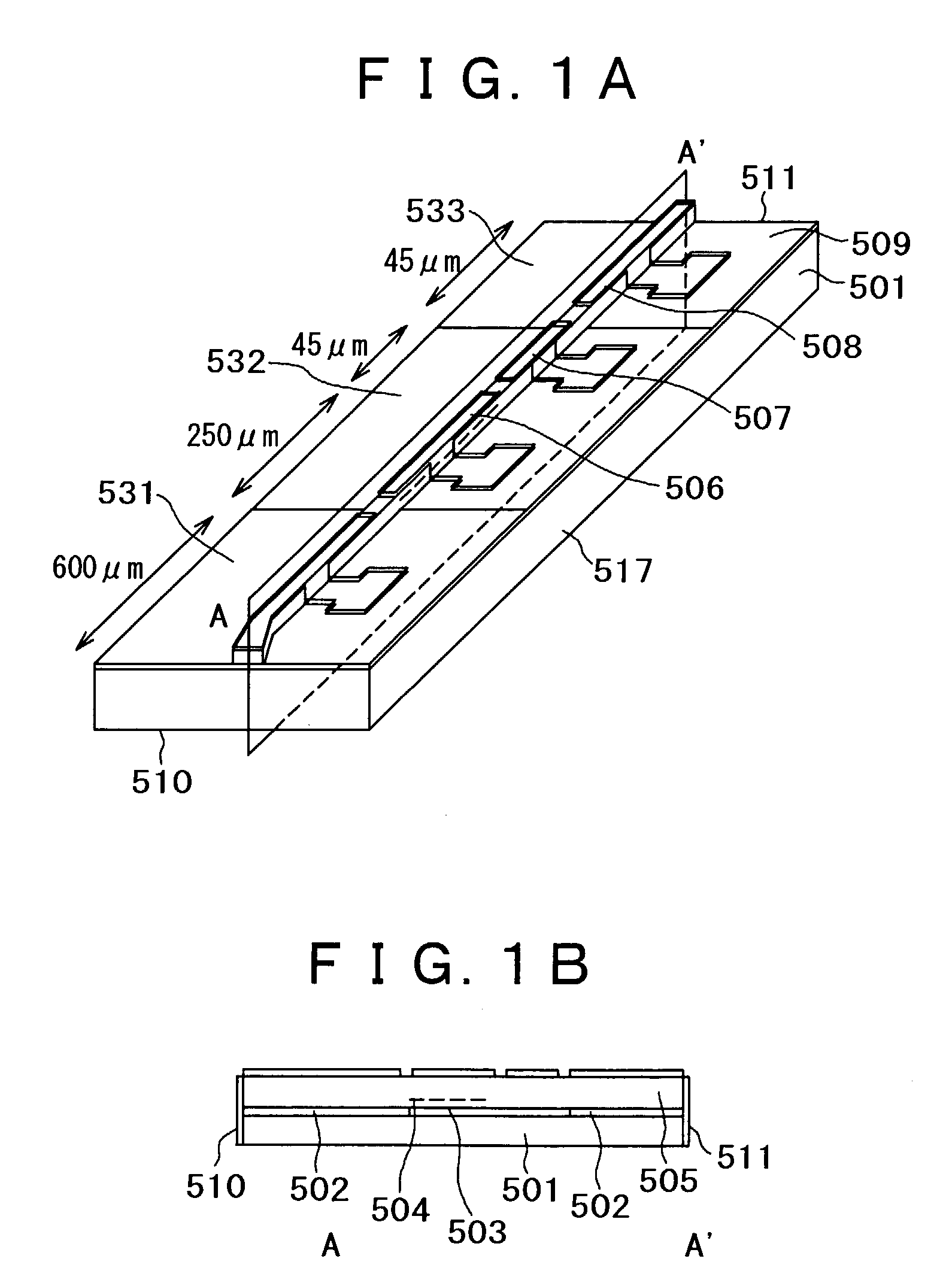
[0025]FIG. 1 is a view showing an example of fabrication of the semiconductor laser in which a 1.55 μm band distributed reflection type laser and an optical amplifier are integrated according to a first preferred embodiment of the present invention and whose oscillation wavelength can be varied with the electric signal. Continuous tunable wavelength characteristics of the distributed reflection type laser are determined by the longitudinal-mode hopping of the laser. The interval of the laser longitudinal-mode hopping ΔλDBR is dependent on a region length L and is given by the equation:

ΔλDBR=λ2 / 2(naLa+npLp)  (1)

[0026]Here, λ denotes the oscillation wavelength, n denotes the optical refractive index of the laser medium, and suffixes (a) and (p) represent an active region and a phase adjustment region, respectively. The expression has a close relation to a fact that phase variation quantity Δφt of the laser oscillation mode in the active region accompanying a wavelength variation of Δλ...

embodiment 2

[0038]FIGS. 6A and 6B show a laser having a structure similar to that of the preferred Embodiment 1, wherein the active region length is shortened to 33 μm to effect expansion of the continuous tunable wavelength range. A basic structure and fabrication of the device are almost similar to those of Embodiment 1. The main differences in designing the laser are the following points: (1) an optical coupling coefficient of the diffraction grating was enlarged to 200 cm−1 in order to compensate for the decrease in laser gain that accompanied the shortening of the active region, and (2) the distributed reflector is made to be such that the phases of two diffraction grating regions located in front of and in the rear of the active layer are reversed to each other, realizing the so-called λ / 4 phase-shift type grating, in order to stabilize the single axial mode oscillation in the vicinity of the Bragg wavelength.

[0039]With the laser according to this preferred embodiment of the present inven...

embodiment 3

[0041]FIG. 7 shows a configuration shown in Embodiment 2, wherein four distributed reflection lasers 805 each having a different wavelength range are integrated into an array in a side by side manner. Using a known 4×1 optical multiplexer 804 that uses a multi-mode interference waveguide, the outputs of the lasers are guided to an optical amplifier 803 that is monolithically integrated with an output waveguide thereof. In this preferred configuration, a different point from the configuration of the conventional distributed feedback laser array is that, as shown in the figure, wavelength controlling terminals 807 and phase controlling terminals 806 of the lasers are connected to common terminals, respectively. This configuration becomes feasible for the following reasons: (1) two or more lasers are not operated simultaneously, and (2) dead current is an order of 90 mA or less at a maximum because the wavelength controlling current and the phase controlling current are 30 mA or less, ...


PUM


Abstract

A device structure whereby an excellent tunable laser does not require a highly complicated wavelength control circuit, and delivers a high output, and excels in wavelength stability; and a structure of an optical module incorporating the laser; and a method for manufacturing the laser and the optical module. The wavelength of the laser is varied continuously with the single electric signal in the tunable wavelength range by setting the laser resonator length, the electric driving conditions of the laser at the time of tuning the wavelength, and the operating temperature to be in appropriate ranges, respectively. The device structure whereby improved laser gain, decreased electric resistance, and reduced heat resistance is attained by setting the waveguide width, particularly at part of or all parts of the laser resonator waveguide, to a wide width that allows multiple transverse modes to be sustained and setting both the width and the laser resonator length to appropriate values, respectively. By employing a self-image-formation effect resulting from the multi-mode interference effect, mode conversion loss in the laser resonator is reduced and, connection with an optical fiber is facilitated because the light intensity distribution at an emitting facet of the laser becomes a single-peaked lowest-order mode.

Description

BACKGROUND OF THE INVENTION[0001]1. Field of the Invention[0002]The present invention relates to a semiconductor laser, especially to a semiconductor laser for communication systems that has a short laser cavity length and is suited for a wavelength-tunable operation in a wide wavelength range, and to an optical module of the same.[0003]2. Description of the Related Art[0004]It is known that, in the tunable distributed reflection type semiconductor laser in which an active waveguide having a function of light amplification and a waveguide reflector that has a diffraction grating and adjusts an emission wavelength by varying a reflection wavelength range are connected monolithically in a traveling direction of light, hopping of the laser axial mode occurs as the wavelength varies. This phenomenon can be explained by that a mode hopping spacing Δλ of the distributed reflection type laser without a phase adjustment region and an active region length La are linked to each other by a rel...

Claims


Application Information

Patent Timeline
IPC IPC(8): H01S5/026H01S5/00H01S5/40H01S5/022H01S5/125
CPCB82Y20/00H01S5/06256H01S5/22H01S5/026H01S5/0265H01S5/028H01S5/1014H01S5/1039H01S5/34306H01S5/4012H01S5/4087
Inventor AOKI, MASAHIRO
Owner HITACHI LTD
Why Eureka
Try Eureka