
CPO regenerated lean NOx trap with no moving parts

a technology of nox traps and moving parts, which is applied in the direction of engines, mechanical equipment, machines/engines, etc., can solve the problems of significant significant waste of fuel, and inability to operate without leakage of high-temperature exhaust valves, so as to reduce the size and complexity of nox-reducing equipment for engine exhaust, avoid waste of regeneration gas, and improve the effect of nox to nitrogen reduction

Inactive Publication Date: 2005-10-18
SHELL OIL CO
View PDF10 Cites 69 Cited by
  • Summary
  • Abstract
  • Description
  • Claims
  • Application Information

AI Technical Summary

Benefits of technology

[0005]Objects of the invention include: eliminating high temperature valves in exhaust deNOx regenerative adsorption beds; improvement in reduction of NOx to nitrogen and other harmless gases in internal combustion engine exhaust; reducing the size and complexity of NOx-reducing equipment for engine exhaust; simplified equipment capable of meeting EPA 2007 NOx emission requirements; and avoiding waste of regeneration gas that occurs due to valve leakage in alternating NOx adsorption systems.
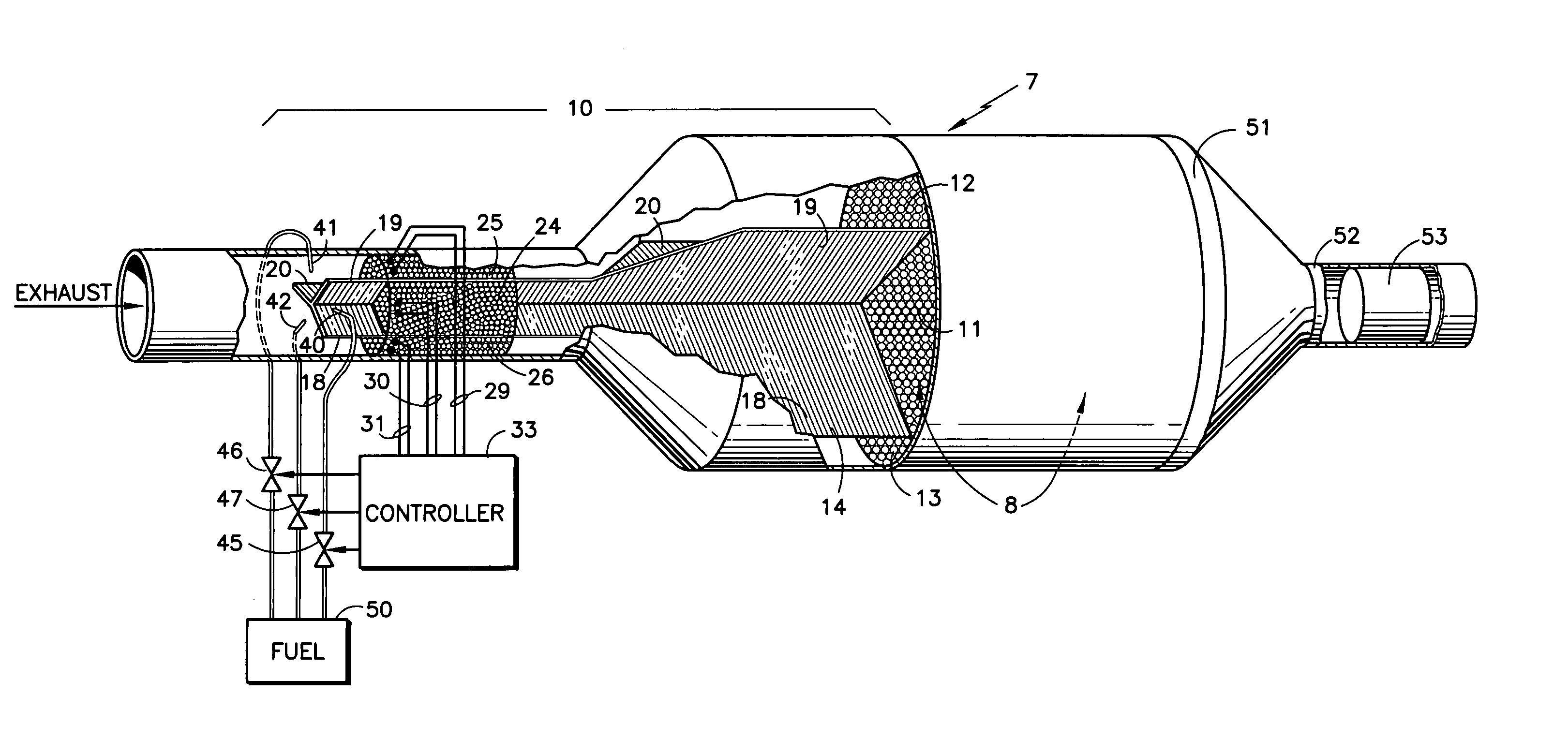
[0006]This invention is predicated in part on the realization that injection of fuel into one of several exhaust inlet zones to a single low temperature LNT catalyst creates sufficient back pressure, due to the approximately 16 fold volume expansion of the injected fuel, to divert more exhaust to the others of the zones. As an example, in a three-zone embodiment, the diversion reduces the share of exhaust in each zone from 33%, when none of the zones are in the regeneration mode, to on the order of 25% of the total exhaust, as a result of the increased flow and temperature resulting from conversion of fuel to syngas. The small portion of exhaust provides oxygen, steam (humidity) and heat, that are required for the CPO in that same zone to partially oxidize the diesel exhaust and generate syngas (H2 and CO) for lean NOx trap (LNT) regeneration.
[0008]According to the invention further, each reformer catalyst may have its own electric heater which a controller will energize only in timed relation with the injection of fuel into the corresponding zone; in accordance with another embodiment of the invention, a single electric heater for all reformers is operated in timed relationship with the injection of fuel into any of the zones; in a third embodiment, a single electric heater for all reformers is left on at all times, whereby to keep the reformers at a light-off temperature for smoother and more reliable operation.

Problems solved by technology

Heretofore, such high temperature exhaust valves have been unable to operate without leakage.
Because there may be up to 15% oxygen in the engine exhaust, which oxygen will react with the hydrogen and carbon monoxide in the regeneration gas, a significant amount of regeneration gas is wastefully consumed by being combined with oxygen due to the leaks in the valves, which in turn wastes significant fuel.
High temperature valves required in controlling the exhaust and regeneration gas of a deNOx system are expensive and bulky.

Method used


Image

  • CPO regenerated lean NOx trap with no moving parts
  • CPO regenerated lean NOx trap with no moving parts

Examples


Embodiment Construction

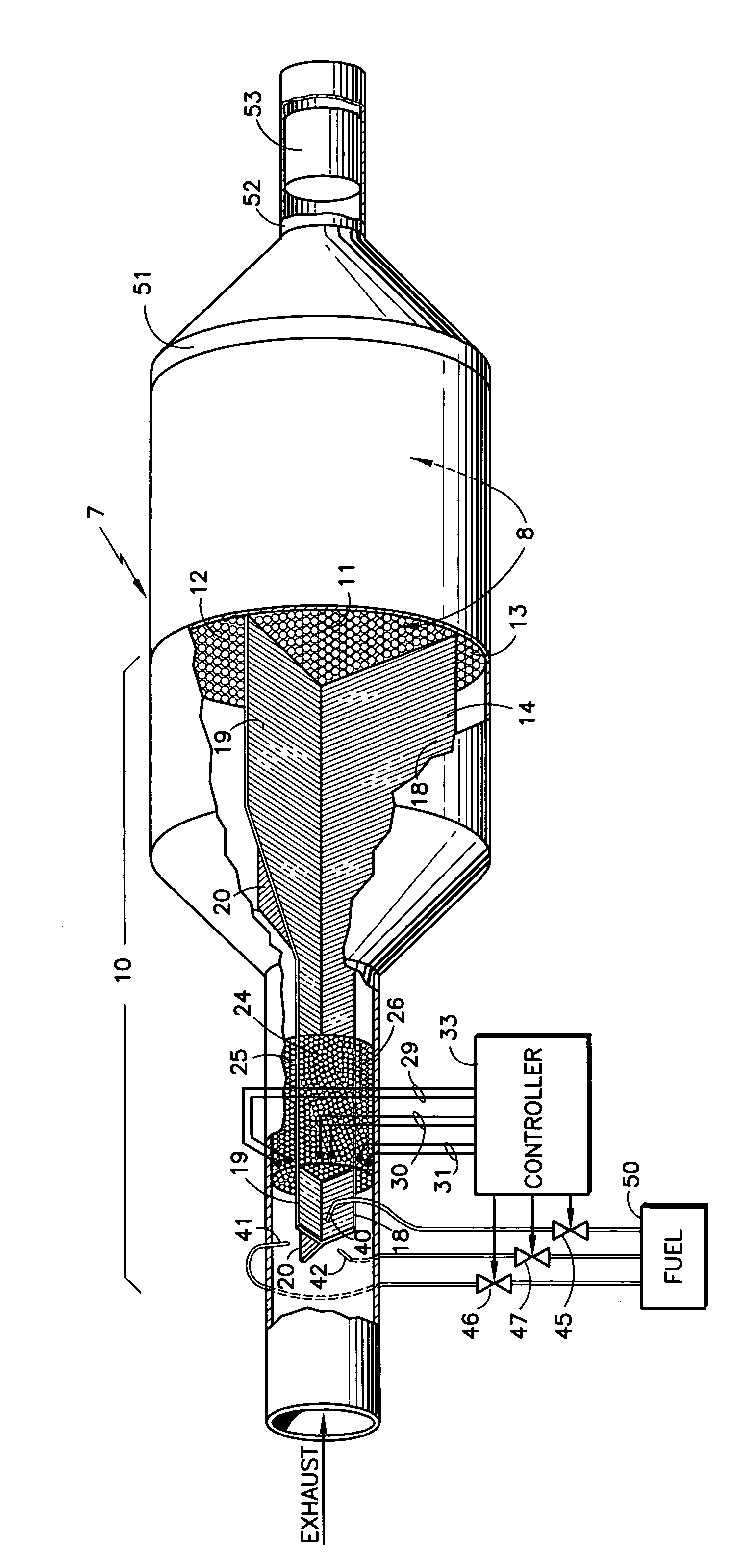
[0011]Referring to the FIGURE, a static LNT deNOx system 7 has a single lean deNOx catalyst 8, such as barium carbonate on cordierite support, having an inlet manifold 10 which is divided into three zones 11–13 by baffles 18–20. Between the baffles 18–20, there are conventional diesel particulate filters 14 (not shown for clarity), which may comprise cordierite or silicon carbide. Each zone has a partial oxidation catalyst 24–26, such as platinum or other noble metal or alloy. At the upstream end of each catalyst 24–26, there is disposed an electric heater element (not shown) which is energized by corresponding sets of wires 29–31 in response to a controller 33.

[0012]Each of the zones has a fuel injection nozzle, each connected by a corresponding pipe 40–42 to a corresponding valve 45–47 which supplies fuel from a source 50, such as the on-board primary fuel tank of the internal combustion engine.

[0013]The controller 33, may, for example, energize the wires 29 to energize the heater...


PUM


Abstract

A single lean NOx trap (8) has an inlet manifold (10) with baffles (18–20) to divide the inlet manifold into three flow paths (11–13). Each flow path has a thermal reformer (24–26; CPO, (POX, or ATR) with an electric heater provided electric power by related lines (29–31). Fuel from a source (50) is controlled (45–46) to apply pulses of fuel through nozzles (40–42) into each corresponding path (11–13) in turn. A plurality of diesel particulate filters (14) are disposed in the flow paths (11–13) upstream of the lean NOx trap (8). A diesel oxidation catalyst (53) is disposed downstream of the lean NOx trap.

Description

TECHNICAL FIELD[0001]This invention relates to apparatus for reducing oxides of nitrogen in the exhaust of an internal combustion engine, having a single, catalytic lean NOx trap (LNT) which has an inlet manifold dividing the flow into a plurality of separate flows between separation baffles, each of the separate flows having a thermal reformer, such as a catalytic partial oxidizer (CPO) catalyst, with optional means for heating the upstream end of the CPO catalyst and a nozzle for periodically injecting engine fuel, the CPO catalyst forming a hydrogen containing gas to regenerate the related portion of the LNT catalyst.BACKGROUND ART[0002]In one type of known system for reducing oxides of nitrogen in the exhaust of internal combustion engines (deNOx), it is known to have a pair of NOx adsorbent traps, such as with a barium carbonate adsorbent, one of which receives exhaust gas while the other receives desorbent (regeneration) gas, typically hydrogen containing reformate from a refo...

Claims


Application Information

Patent Timeline
IPC IPC(8): F01N3/00F01N3/035F01N3/08F01N3/36F01N13/02F01N13/04
CPCF01N3/035F01N3/0814F01N3/0821F01N3/0842F01N3/0871F01N3/0878F01N13/017F01N13/009F01N3/36F01N2240/16F01N2240/20F01N2240/30F01N2250/02F01N2250/12F01N2250/14F01N2330/06F01N2410/00F01N2410/04F01N2570/14F01N2610/1453Y02T10/24Y02A50/20Y02T10/12
Inventor WNUCK, WAYNE G.LIU, KE
Owner SHELL OIL CO
Learn More