
Programmable peaking receiver and method

a receiver and programmable technology, applied in the field of communication systems, can solve the problems of data communication systems facing many challenges today, data transmission speeds are increasing, and the size of integrated circuits is being reduced rapidly

Inactive Publication Date: 2005-08-30
MARVELL ASIA PTE LTD
View PDF32 Cites 35 Cited by
  • Summary
  • Abstract
  • Description
  • Claims
  • Application Information

AI Technical Summary

Benefits of technology

The patent describes a method and system for controlling the sensitivity of a receiver by adjusting the peaking function, which is the sensitivity of the receiver over a limited range of signal frequencies. This can be used to compensate for signal loss in the transmission medium. The system includes input transistors, tail transistors, and a programmable impedance element to adjust the peaking function. The invention provides a programmable peaking receiver that compensates for signal loss in the transmission medium.

Problems solved by technology

Data communication systems face many challenges today.
The sizes of integrated circuit are being reduced rapidly, and data transmission speeds are increasing, requiring decreases in operating voltages and current levels, while signal losses increase over transmission media, and higher noise appears.
The challenges are especially great in high speed serial data communications where high data transfer rates are required in difficult environments in which signals are highly attenuated over the communication channel and much noise is present due to cross-coupled interference (“cross-talk”) among others.
While data signal receivers generally receive signals by sampling the input signal at the center of the period of an active signal at a time halfway between up and down signal transitions or halfway between down and up signal transitions, jitter introduces uncertainty to that determination, such that occasionally a data transition can occur at the time that coincides with the time that the input signal is sampled, thus causing the input signal to be sampled incorrectly.
When a high amount of jitter is present, high data rate signals cannot be received reliably to keep bit error rates within tolerable limits.
Jitter arises because insertion loss (i.e. the attenuation of a transmitted signal over a transmission medium) increases with frequency, causing signals to take longer to transition between levels, making it more difficult to receive higher frequency signals.
Jitter may also be caused by inadequate control over the impedances of the transmitter and receiver, such as may arise from the impedance of an integrated circuit package.
In addition, jitter arises from signal attenuation due to inter-symbol interference (ISI), when irregular data patterns occur.
Although many prior approaches have been used to help overcome signal integrity problems, each such approach is deficient in one way or another.
A serious drawback to this approach, which limits its ability to be utilized, concerns cross-coupled interference.
The drive strength of the transmitter is limited to a level above which cross-coupled interference to closely situated devices becomes intolerable.
Thus, the transmitter drive strength cannot be arbitrarily increased.
For one, the driver is bulky, consuming much circuit area, and also consumes much power.
In addition, the equalization is neither adjustable nor tunable, such that over or under-equalization at the transmitter end can actually cause jitter at the receiver end to exceed threshold.
Another problem of performing equalization at the transmitter end is that it may not always solve problems that appear at the receiver end.
The disadvantages of using a FIR type equalizer are complicated design and operation, and high power overhead, i.e. the amount of power used to implement the FIR, as opposed to the power going into the received signal.
However, the tuned peaking amplifier designs described above cannot be readily used in SerDes cores.

Method used


Image

  • Programmable peaking receiver and method
  • Programmable peaking receiver and method
  • Programmable peaking receiver and method

Examples


first embodiment

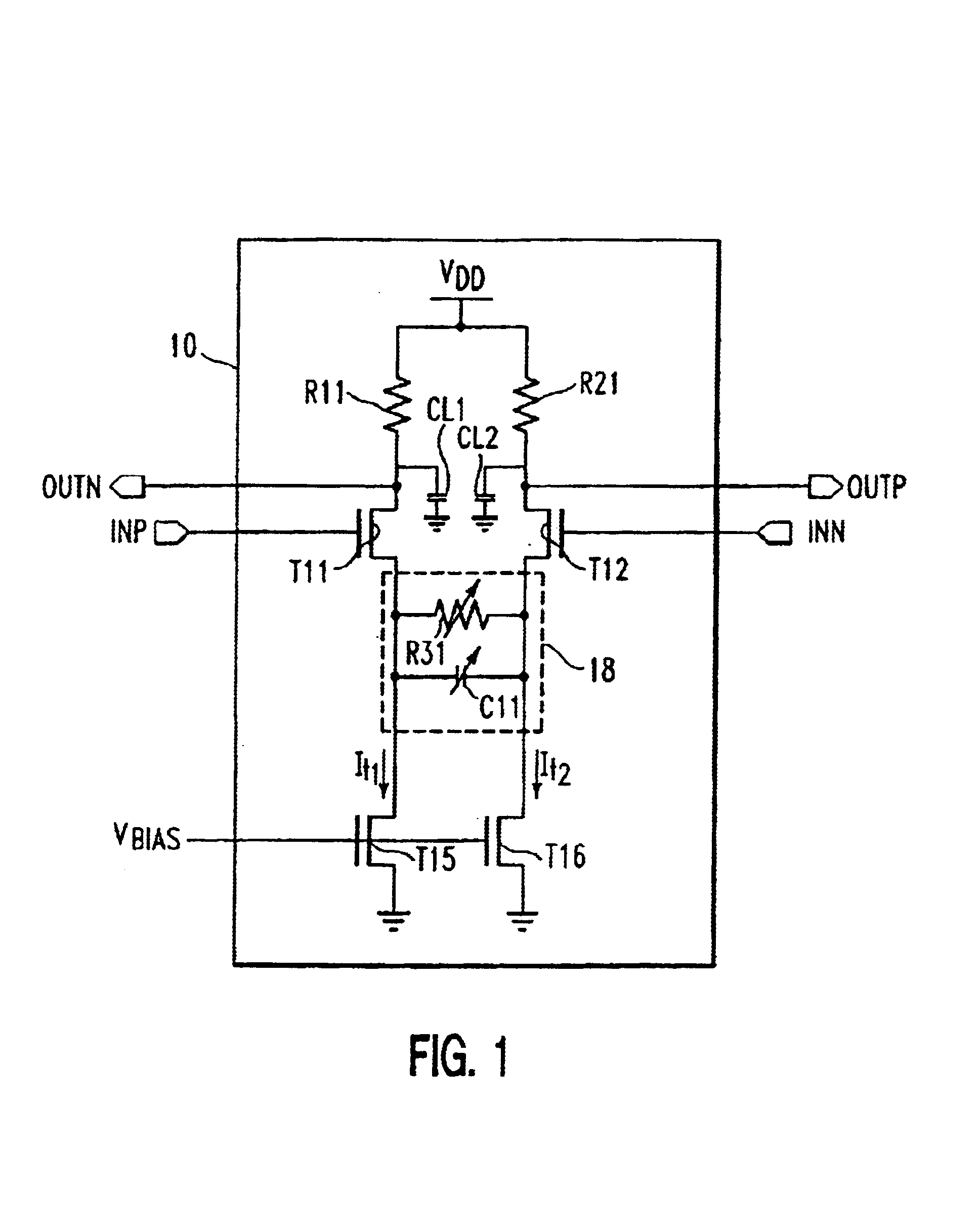
[0028]an on-chip programmable peaking receiver 10 is shown in FIG. 1. The receiver 10 is known as a “peaking” receiver because there is a strong peak in sensitivity over a relatively narrow range of frequencies: in this case, in the high frequency range of the signal spectrum. When a peaking receiver boosts sensitivity at high frequency relative to low frequency, it can help compensate for inter-symbol interference (ISI), since a cause of ISI is high frequency roll-off of the signal spectrum input to the receiver, among others. A peaking receiver can also help suppress cross-talk noise, which includes interference arising from proximity to other transmitters and / or other receivers and signal lines, or which can be self-generated, e.g. as spurious harmonics of the signal. In addition, because a peaking receiver has increased sensitivity over a particular range of frequencies of interest, such peaking receiver can receive signals transmitted at lower transmission power. Lowered transm...

second embodiment

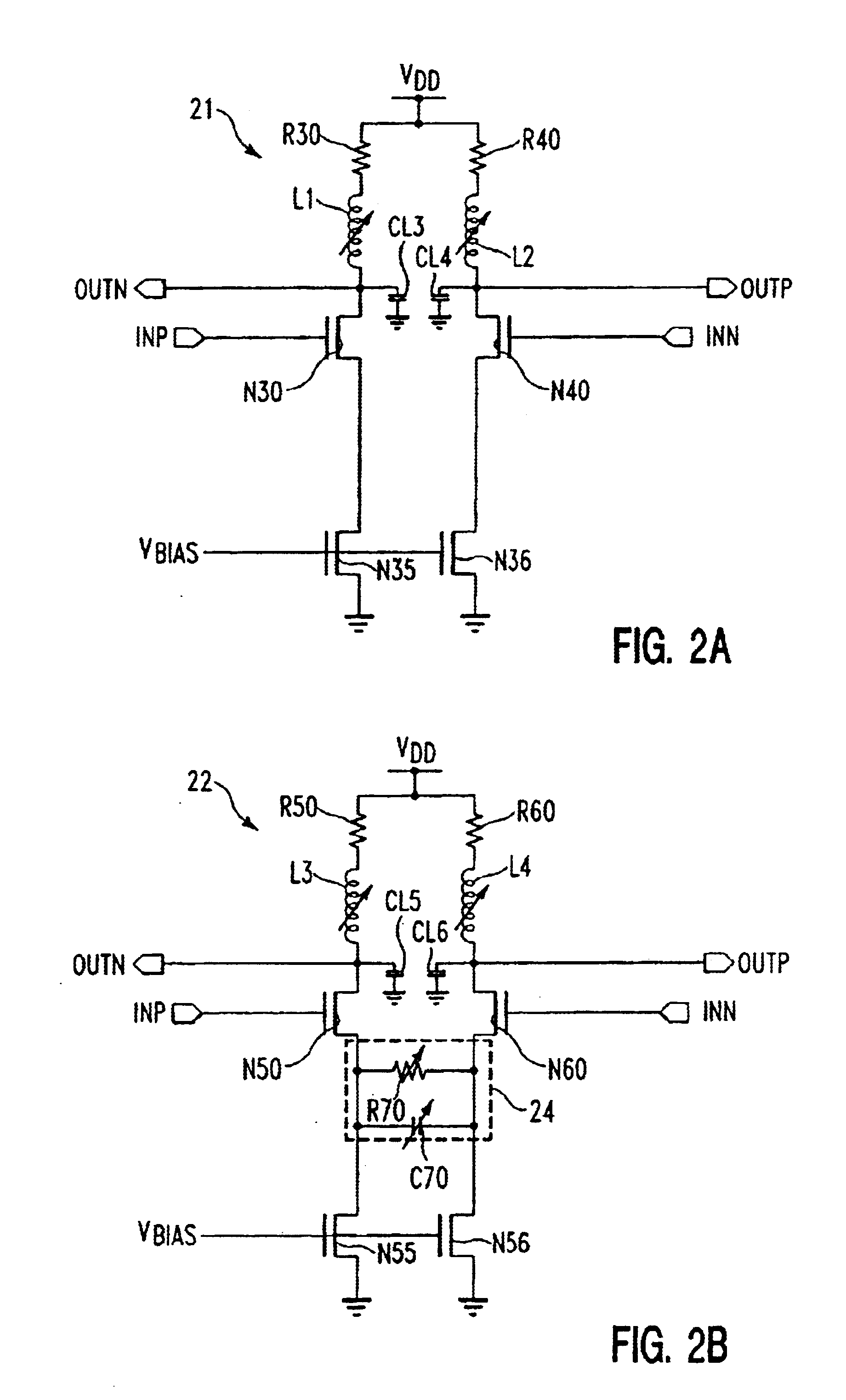
[0035]an on-chip programmable peaking differential signal receiver 21 is shown in FIG. 2A. In this embodiment, a pair of on-chip programmably adjustable inductive elements L1 and L2 are provided as load elements to enable the frequency peaking function of the receiver 21 to be adjusted. The impedance Z of an inductor varies directly with frequency, i.e. Z(L)=jÏ□L. Therefore, adjustable inductive elements L1 and L2 present load impedances that increase with frequency, to counteract high frequency rolloff that occurs otherwise. For example, high frequency rolloff occurs due to load capacitors CL3 and CL4. Such load capacitors CL3 and CL4, which include, in part, parasitic capacitances arising during fabrication, have impedances (1 / jÏ□C) that become lower at high frequencies, thus reducing the voltage drop across the load, and thereby reducing the differential output voltages OUTN and OUTP. By making the inductive load elements L1 and L2 programmably adjustable, the receiver 21 can be ...


PUM


Abstract

Methods and structures are disclosed herein for programmably adjusting a peaking function of a differential signal receiver. The disclosed method includes inputting a pair of differential signals to a pair of input transistors coupled to conduct currents differentially between a pair of load impedances and a pair of tail transistors. The impedance of an adjustable shunt impedance element between the tail transistors of the receiver is varied by programming signal input, such that higher current is conducted over a peaking range of frequencies. In a disclosed structural embodiment, an integrated circuit is provided having a programmable peaking receiver. The programmable peaking receiver includes a pair of input transistors coupled to conduct differentially according to a pair of differential inputs applied to the pair of input transistors. Each of the input transistors produces an output in accordance with the differential input applied thereto. The programmable peaking receiver also includes a pair of tail transistors, coupled to draw current from the input transistors, and a programmably adjustable impedance element coupled between current-conducting nodes of the tail transistors. The impedance of the programmably adjustable impedance element is thereby adjustable in response to programming signal input to adjust a peaking function of the programmable peaking receiver.

Description

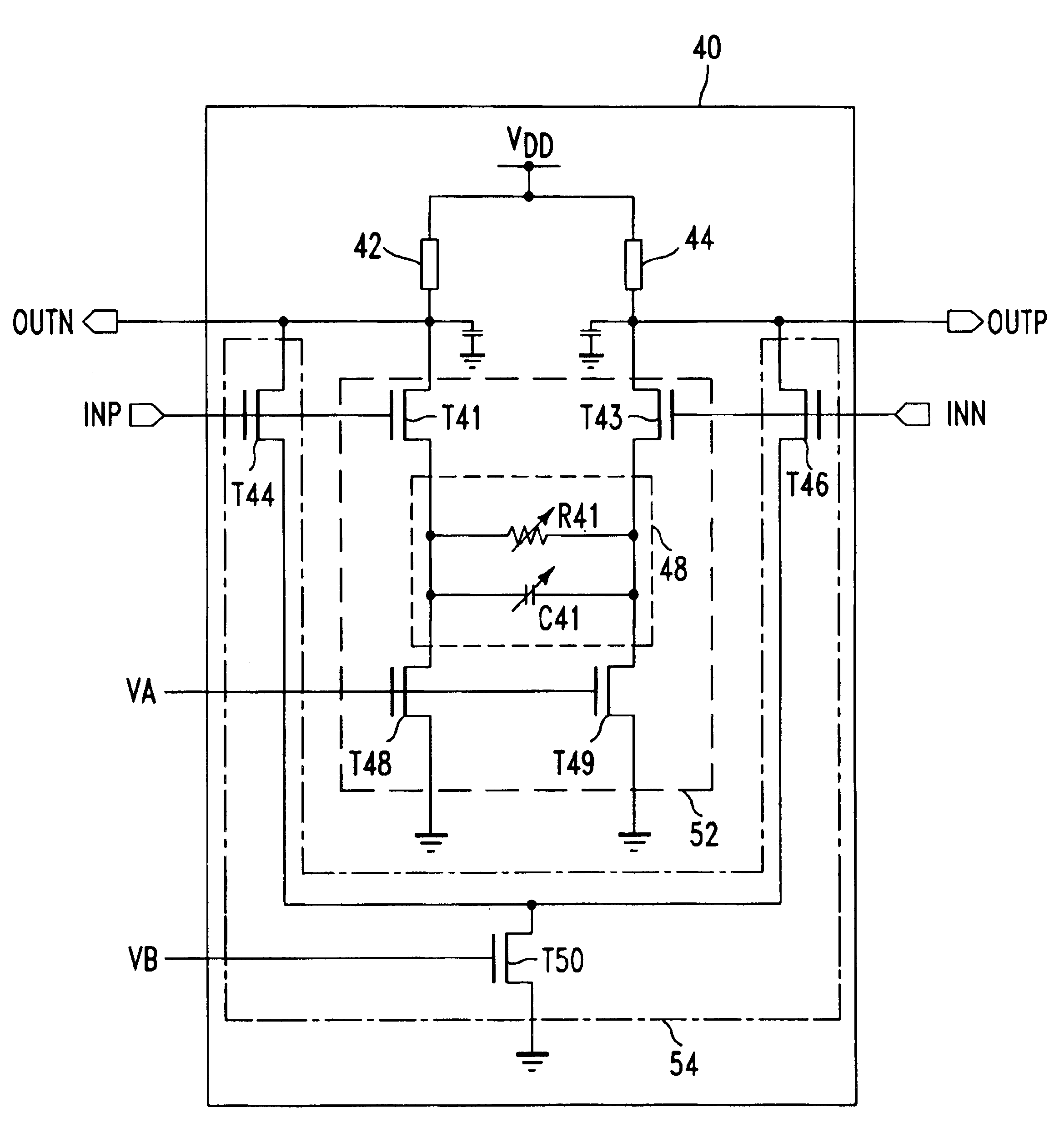
BACKGROUND OF INVENTION[0001]This invention relates to communication systems and more specifically to a system and method in which a receiver of an integrated circuit has a peaking function that is adjustable by varying one or more programming signal inputs to the receiver.[0002]Data communication systems face many challenges today. The sizes of integrated circuit are being reduced rapidly, and data transmission speeds are increasing, requiring decreases in operating voltages and current levels, while signal losses increase over transmission media, and higher noise appears. The challenges are especially great in high speed serial data communications where high data transfer rates are required in difficult environments in which signals are highly attenuated over the communication channel and much noise is present due to cross-coupled interference (“cross-talk”) among others. In addition, a transmitter or a receiver, as designed, may need to be capable of transmitting, or receiving, c...

Claims


Application Information

Patent Timeline
Patent Type & Authority Patents(United States)
IPC IPC(8): H04L25/02
CPCH04L25/0272H04L25/0278H04L25/0294H04L25/03885
Inventor HSU, LOUIS L.SELANDER, KARL D.SORNA, MICHAEL A.WASHBURN, WILLIAM F.XU, HUIHAO H.ZIER, STEVEN J.
Owner MARVELL ASIA PTE LTD
Learn More