
Lighting apparatus and light emitting diode device thereof

A technology of light-emitting diodes and lighting devices, applied in the field of light-emitting diodes or red light-emitting diodes, and the phenomenon of brightness attenuation, can solve the problems of lighting brightness changes, light attenuation characteristics, large light attenuation characteristics, and serious luminous efficiency of decreasing degree, and achieves a compensation measure. The effect of decay

Inactive Publication Date: 2012-07-18
EVERLIGHT ELECTRONICS
View PDF4 Cites 3 Cited by
  • Summary
  • Abstract
  • Description
  • Claims
  • Application Information

AI Technical Summary

Problems solved by technology

Moreover, the light-emitting diode of the red-light chip, because of its light decay characteristic is larger than that of the light-emitting diode of the blue-light chip, when the ambient temperature rises, the luminous efficiency of the light-emitting diode of the red chip also decreases. It will decrease accordingly, and the degree of decrease is more serious than the luminous efficiency of the light-emitting diode of the blue light chip
As a result, the lighting brightness provided by this known lighting device will also change greatly, seriously affecting the performance of the lighting device

Method used


Image

  • Lighting apparatus and light emitting diode device thereof
  • Lighting apparatus and light emitting diode device thereof
  • Lighting apparatus and light emitting diode device thereof

Examples


Embodiment Construction

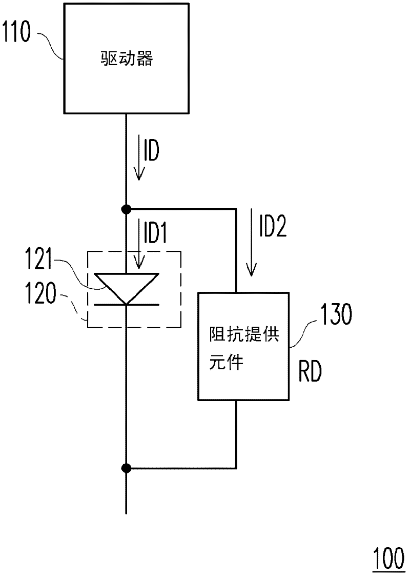
[0030] Please refer to figure 1 , figure 1 A schematic diagram of a light emitting diode device 100 according to an embodiment of the present invention is shown. The LED device 100 includes a driver 110 , a red LED string 120 and an impedance providing element 130 . The driver 110 is used for generating a driving current ID. The driver 110 can be constructed using various current generators such as a voltage-controlled current source, an independent current source, etc. that can generate a stable driving current ID. The current generator for generating the stable driving current ID is an electronic device well known to those skilled in the art, and its implementation details will not be repeated here.

[0031] The red light emitting diode string 120 includes N light emitting diodes 121 connected in series, where N is a positive integer (in figure 1 In the illustration of , N is equal to 1). certainly, figure 1 The illustration above is just an example. When the number of...


PUM


Abstract

The present invention provides a light emitting diode (LED) device. The LED device includes at least a red light emitting diode, at least an impedance-providing component and a driver. The red light emitting diode has an internal resistance. The impedance-providing component coupled in parallel with the red light emitting diode. The impedance-providing component provides a shunt impedance having a value that varies in positive proportion with a variation in an ambient temperature. The driver is respectively coupled in series with the red LED and the impedance-providing component. The driver provides a drive current divided to flow through the first LED and the at least one impedance-providing component according to the shunt impedance and the internal impedance.

Description

technical field [0001] The present invention relates to an illuminating device and the structure of the light-emitting diode device, and in particular relates to a method for reducing the brightness attenuation phenomenon of light-emitting diodes or red light-emitting diodes with serious light decay characteristics due to temperature rise. Background technique [0002] With the demand for environmental protection, it has become an irreversible trend to use light-emitting diodes to construct lighting fixtures that provide lighting in people's daily life. However, in the known technology, LED lighting devices for providing warm lighting are usually made of LEDs with blue and red chips and yellow and red phosphors. In this known lighting device, as the operating time increases, the temperature of the environment where it is located will rise accordingly. Moreover, the light-emitting diode of the red-light chip, because of its light decay characteristic is larger than that of t...

Claims


Application Information

Patent Timeline
Patent Type & Authority Applications(China)
IPC IPC(8): H05B37/00H05B44/00
CPCH05B33/0872H05B33/083H05B45/20H05B45/48
Inventor 李顺昌赵自皓马卿云
Owner EVERLIGHT ELECTRONICS
Learn More