
Electrical double filter structure

a filter structure and double filter technology, applied in the field of electric double filter structure, can solve the problems of difficult to obtain good broadband characteristics in a difficult to reduce the size of the filter, and difficult to achieve good broadband characteristics in the real implementation of the filter structure. , to achieve the effect of reducing the parasitics of the transmission line structure, reducing the size of the filter, and improving the filter structur

Active Publication Date: 2013-08-08
ADVANTEST CORP
View PDF4 Cites 4 Cited by
  • Summary
  • Abstract
  • Description
  • Claims
  • Application Information

AI Technical Summary

Benefits of technology

The present invention provides a filter structure that includes two electrically-independent filter core structures that reduces the space-consumption of filters and improves filter characteristics. The use of interleaved arrangement of transmission line structures allows for a space-saving implementation of the filter core structures and includes vertical structures, like via structures, that give an additional degree of freedom in the design. The shunt impedance elements of the first filter core structure are arranged in different conducting layers of the multi-layer structure, and the second filter core structure is configured to forward a second signal, which is electrically separate from the first signal. The patent text also describes how the filter structure can be combined with an impedance scaling of the filter core structure for improved filter characteristics and reduced parasitics of the transmission line structures. Overall, the invention provides a compact, efficient, and high-performing filter structure.

Problems solved by technology

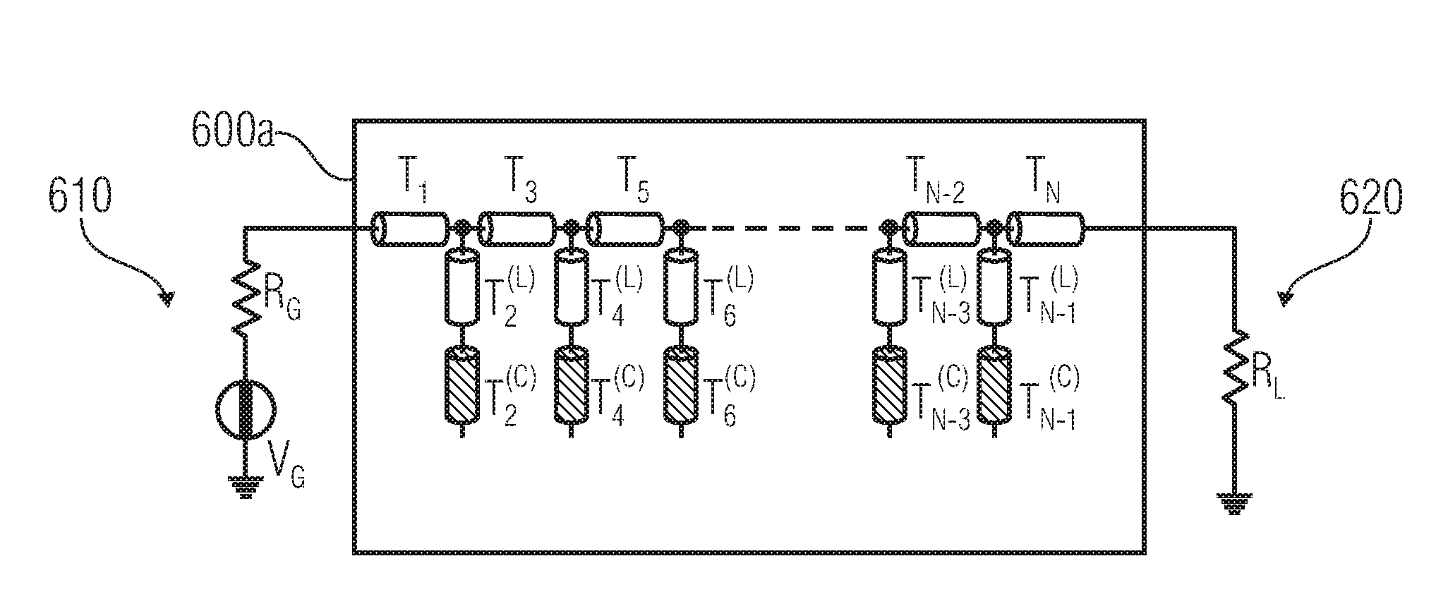
However, it has been found that the implementation of the filter structure 600a according to FIG. 6b with good filter characteristics is problematic in some technologies.
For example, it has been found that it is sometimes difficult to obtain good broadband characteristics in a real implementation of the filter structure 600a.

Method used


Image

  • Electrical double filter structure
  • Electrical double filter structure
  • Electrical double filter structure

Examples


Embodiment Construction

[0045]Reference will now be made in detail to the various embodiments of the present disclosure, examples of which are illustrated in the accompanying drawings. While described in conjunction with these embodiments, it will be understood that they are not intended to limit the disclosure to these embodiments. On the contrary, the disclosure is intended to cover alternatives, modifications and equivalents, which may be included within the spirit and scope of the disclosure as defined by the appended claims. Furthermore, in the following detailed description of the present disclosure, numerous specific details are set forth in order to provide a thorough understanding of the present disclosure. However, it will be understood that the present disclosure may be practiced without these specific details. In other instances, well-known methods, procedures, components, and circuits have not been described in detail so as not to unnecessarily obscure aspects of the present disclosure.

[0046]S...


PUM


Abstract

An electrical filter structure includes a first filter core structure and a second filter core structure. The first filter core structure includes a plurality of shunt impedance elements. Similarly, the second filter core structure includes a plurality of shunt impedance elements. Shunt impedance elements of the first filter core structure are arranged in different conducting layers of a multi-layer structure, and shunt impedance elements of the second filter core structure are arranged in different layers of the multi-layer structure. Transmission lines used to implement the shunt impedance elements are interleaved.

Description

CROSS-REFERENCE TO RELATED APPLICATIONS[0001]This application is a Continuation of and claims priority to International Application No. PCT / EP2010 / 057503, filed on May 28, 2010, titled “ELECTRICAL DOUBLE FILTER STRUCTURE AND ITS MULTI-LAYER IMPLEMENTATION,” by Giovanni Bianchi, which is herein incorporated by referenceFIELD OF THE INVENTION[0002]Embodiments according to the invention are related to an electrical filter structure for forwarding a first electrical signal from a first filter port to a second filter port in a frequency-selective manner, and for forwarding a second electrical signal from a third filter port to a fourth filter port in a frequency-selective manner.[0003]Some embodiments according to the invention are related to a scaled impedance semi-lumped low-pass filter.BACKGROUND OF THE INVENTION[0004]Electrical filter structures are used in many applications. For example, electrical filter structures may be implemented to act as a low-pass filter, as a bandpass filte...

Claims


Application Information

Patent Timeline
IPC IPC(8): H03H7/01
CPCH01P1/20345H03H7/0123H03H7/0138H03H2250/00H03H7/1758H03H2001/0085H01P1/203H03H7/01
Inventor BIANCHI, GIOVANNI
Owner ADVANTEST CORP
Learn More