
Composite oxide powder, a method for producing the same and a catalyst using the same

Inactive Publication Date: 2005-08-23
TOYOTA CENT RES & DEV LAB INC
View PDF18 Cites 30 Cited by
  • Summary
  • Abstract
  • Description
  • Claims
  • Application Information

AI Technical Summary

Benefits of technology

[0008]The present invention has been conceived in view of these circumstances. It is an object of the present invention to provide composite oxide powder having a large specific surface area and a large pore volume even after exposed to high temperature for a long time, without losing characteristics of an oxide of a single metal. It is another object of the present invention to provide a catalyst with excellent durability by suppressing noble metal grain growth during the use at high temperature for a long time.

Problems solved by technology

However, the conventional catalyst comprising CeO2 and Pt or the like loaded on CeO2 is poor in durability in actual exhaust gases because CeO2 is sintered by heat, and cannot be in practical use.
If the heat resistance is not improved without damaging the oxygen storage capability of CeO2, there is a fear that noble metal grains grow and the noble metal catalytic activity declines.

Method used


Image

  • Composite oxide powder, a method for producing the same and a catalyst using the same
  • Composite oxide powder, a method for producing the same and a catalyst using the same
  • Composite oxide powder, a method for producing the same and a catalyst using the same

Examples


example 1

[0105]0.2 mol (75.1 g) of aluminum nitrate 9-hydrate was mixed with 2000 ml of ion exchange water, and dissolved by stirring with a propeller mixer for 5 minutes. Then 304 g (0.5 mol in terms of CeO2) of an aqueous solution containing 28% by weight of cerium nitrate was mixed to the solution and stirred for another 5 minutes.

[0106]177 g of 25% aqueous ammonia was added to the obtained mixed aqueous solution and stirred for another 10 minutes, thereby preparing an aqueous solution containing precipitate. Then an aging step was carried out by applying heat treatment to the aqueous solution containing the precipitate at 120° C. for 2 hours under a pressure of 2 atm, thereby aging the precipitate.

[0107]Then, the aqueous solution containing the aged precipitate was heated at a temperature rising rate of 100° C. / hour and calcined at 400° C. for 5 hours, thereby preparing CeO2—Al2O3 composite oxide powder. The obtained CeO2—Al2O3 composite oxide powder is composed of about 89% by weight of...

example 2

[0108]CeO2—Al2O3 composite oxide powder was prepared in a similar way to Example 1, except that the step of aging the precipitate by applying heat treatment at 120° C. for 2 hours under a pressure of 2 atm was not carried out.

example 3

[0109]Composite oxide powder was prepared in a similar way to Example 1, except that 0.02 mol (5.23 g) of barium nitrate was further added to the mixed aqueous solution of aluminum nitrate 9-hydrate and cerium nitrate and that the amount of 25% aqueous ammonia added was 180 g. The obtained composite oxide powder is composed of about 87 wt % CeO2, about 10 wt % Al2O3 and about 3 wt % BaO.


PUM

PropertyMeasurementUnit
Temperatureaaaaaaaaaa

Abstract

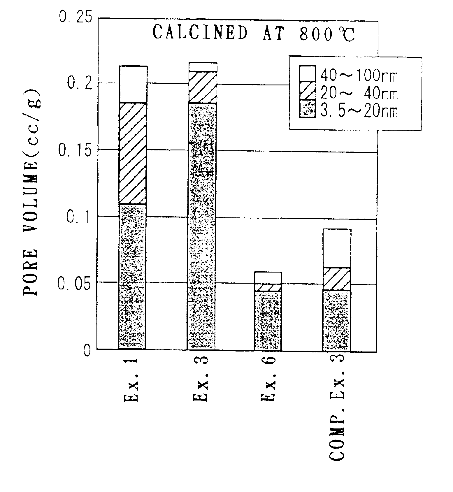
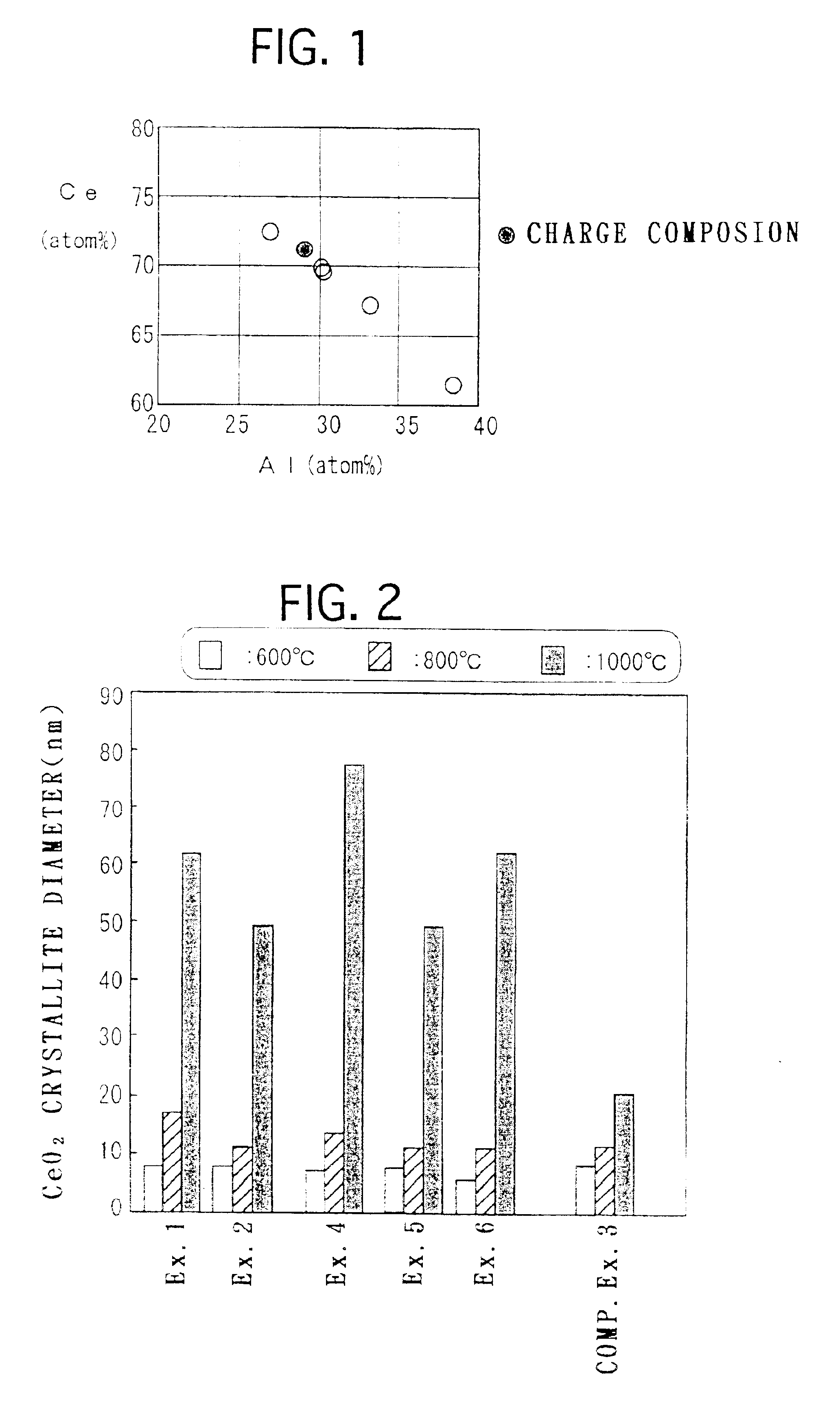
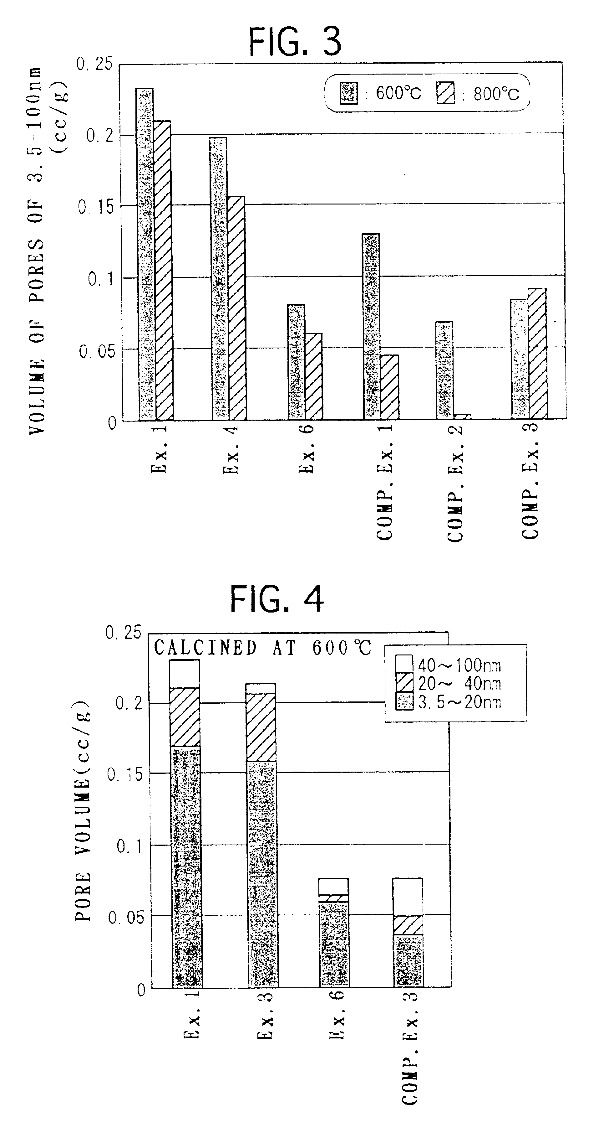
This composite oxide powder can secure a large pore volume even after calcination at high temperature and, when a catalyst is formed by loading a noble metal on this composite oxide powder, noble metal grain growth can be suppressed. The composite oxide powder comprises particles of an oxide of a metal M1 and an oxide of a metal M2 which does not dissolve in the oxide of the metal M1, the oxide of the metal M1 and the oxide of the metal M2 being dispersed at the nanometer level. Since different oxides serve as a barrier to each other, sintering is suppressed. Therefore, in the case of composite oxide powder comprising Ce as a metal M1 and Al as a metal M2, grain growth is small even after exposed to high temperature and pores of 3.5-100 nm secure a volume of 0.07 cc / g or more after calcination at 600° C. for 5 hours and a volume of 0.04 cc / g or more after calcination at 800° C. for 5 hours.

Description

BACKGROUND OF THE INVENTION[0001]1. Field of the Invention[0002]This invention relates to composite oxide powders useful as a catalyst support, a method of producing the same and a catalyst using this composite oxide powder as a catalyst support. This catalyst can be utilized for the purposes of hydrogen generation, exhaust gases purification, and so on.[0003]2. Description of the Related Art[0004]As catalysts for purifying automotive exhaust gases, there have been employed 3-way catalysts so far which oxidize carbon monoxide (CO) and hydrocarbons (HC) and reduce nitrogen oxides (NOx) at the same time to purify exhaust gases. For example, 3-way catalysts are known widely which comprise a heat-resistant honeycomb-shaped supporting base material formed of cordierite, and a catalyst support layer formed of γ—Al2O3 and disposed on the supporting base material, and a noble metal such as platinum (Pt) and rhodium (Rh) loaded on the catalyst support layer.[0005]Catalyst supports used for c...

Claims


Application Information

Patent Timeline
IPC IPC(8): B01J23/00B01J23/10B01D53/94B01J37/03B01J37/00C01B13/14B01J23/54B01J23/63B01J35/10B01J35/00B01D53/86B01J32/00C01B13/36C01B25/00C01B33/00C01F17/00C01G23/00
CPCC01B13/14B82Y30/00B01J37/031B01D53/945B01J23/002B01J23/10B01J2523/00Y10T428/2993Y02T10/22C01P2006/16C01P2006/14C01P2006/13C01P2004/64C01P2002/60Y10T428/2982B01J35/10B01J23/63B01J2523/3712B01J2523/48B01J2523/31B01J2523/25B01J2523/36Y02A50/20Y02T10/12B01J35/60
Inventor HATANAKA, MIHOMORIKAWA, AKIRASUDA, AKIHIKOSOBUKAWA, HIDEOYAMAZAKI, KIYOSHI
Owner TOYOTA CENT RES & DEV LAB INC
Learn More