
Combined advanced finishing and UV laser conditioning process for producing damage resistant optics

a technology of advanced finishing and laser conditioning, applied in the field of optics, can solve the problems of catastrophic damage to the optics, application of this type of remedy, and inability to reduce the initiation of damage sites or mitigating the growth of existing damage sites, so as to reduce damage, reduce damage, and reduce damage. the effect of catastrophic defects

Inactive Publication Date: 2005-07-26
LAWRENCE LIVERMORE NAT SECURITY LLC
View PDF17 Cites 16 Cited by
  • Summary
  • Abstract
  • Description
  • Claims
  • Application Information

AI Technical Summary

Benefits of technology

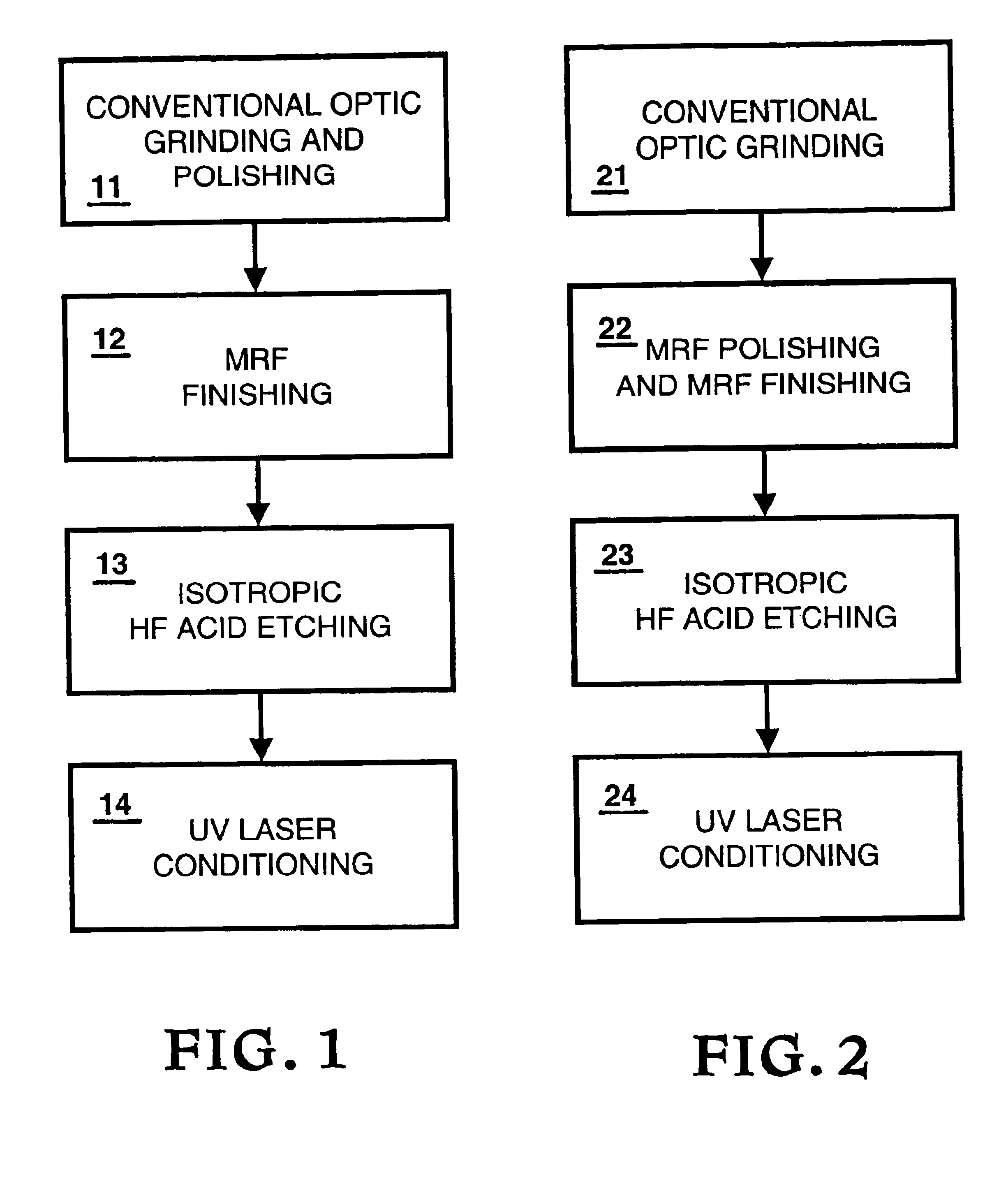
[0016]The present invention provides a method of processing fused silica optics to reduce damage when said fused silica optics are operated in an environment where they will be exposed to high-power light. An embodiment of the invention provides a method for reducing the density of sites on the surface of fused silica optics that are prone to the initiation of laser-induced damage, resulting in optics which have far fewer catastrophic defects, and are better capable of resisting optical deterioration upon exposure to a high-power laser beam. In one embodiment an optical part is prepared by an advanced polishing process that minimizes subsurface defects and then etched in a clean acid solution to remove any surface contaminants. The optical part is then laser conditioned by exposing it to low fluences below levels that normally lead to catastrophic growth of damage. When the optic is then irradiated at its high fluence design limit, the concentration of catastrophic damage sites that form on the surface of the optic is greatly reduced.
[0017]A feature of the invention is to reduce of initiation of catastrophic damage on the surface of fused silica optics, such that the optics can survive prolonged exposure to high-power laser beams having an ultraviolet wavelength of about 360 nm or less.
[0018]Another feature of the invention is to substantially improve the resistance to optical deterioration of optical components made of fused silica, such that these optical components can survive prolonged exposure to high-power ultraviolet irradiation. The invention enables such improvement in the optical components with minimum change in the manufacturing process for said optical components.
[0019]Another feature of the invention is to substantially improve the resistance to optical deterioration of high-energy laser components made of fused silica for applications to UV / DUV / EUV lithography, especially in semiconductor manufacturing.
[0020]There are many commercial lasers that use light wavelengths at 360 nanometers or less. Another feature of the invention is to substantially improve the resistance to optical deterioration of laser components in these devices, since the chief limiting issue for laser materials is their laser damage performance.

Problems solved by technology

However, a method for reducing the initiation of damage sites or mitigating the growth of existing damage sites is not provided.
However, it is not apparent that such a procedure would work for the fused silica component particularly at the ultraviolet wavelength of 355 nm.
However, because there are many possible mechanisms that lead to damage, as discussed by Milan, et al. in U.S. Pat. No. 3,999,865, it is not apparent that the apparatus described by Siekhaus in U.S. Pat. No. 4,667,101 will be able to significantly reduce the initiation of damage sites when a finished fused silica optic is exposed to a high-power ultraviolet laser.
One cannot apply this type of remedy in our case because to do so would quickly result in catastrophic damage to the optic.
Laser damage in these multilayers has been correlated with nodule defects, stemming chiefly from the deposition parameters associated with the high index component.
Therefore, the main mechanism for laser conditioning cannot exist and it then becomes difficult to imply in an obvious manner that laser conditioning, in any form, can take place for bulk fused silica.
Unfortunately, no suitable methods have been shown to significantly reduce the initiation of damage sites when fused silica optics are exposed to high-power lasers at these wavelengths.

Method used


Image

  • Combined advanced finishing and UV laser conditioning process for producing damage resistant optics

Examples


Embodiment Construction

[0025]Referring now to the drawings, to the following detailed information, and to incorporated materials; a detailed description of the invention, including specific embodiments, are described. The description of the specific embodiments, together with the general description of the invention, serve to explain the principles of the invention.

[0026]This invention relates to methods for reducing the initiation of laser-induced damage on the surface of fused silica optics in environments where they are exposed to high-power ultraviolet light having a wavelength of about 360 nm or less, e.g. a YAG third harmonic (355 nm, oftentimes referred to as 3ω) laser beam, an excimer laser beam, or some other high-power ultraviolet laser beam such as that intended for the National Ignition Facility. More specifically, the invention relates to methods for reducing the initiation of surface damage sites that lead to catastrophic failure of the fused silica optics. Further, the invention relates to ...


PUM

PropertyMeasurementUnit
wavelengthaaaaaaaaaa
ultraviolet wavelengthaaaaaaaaaa

Abstract

A method for reducing the density of sites on the surface of fused silica optics that are prone to the initiation of laser-induced damage, resulting in optics which have far fewer catastrophic defects, and are better capable of resisting optical deterioration upon exposure to a high-power laser beam.

Description

CROSS-REFERENCE TO RELATED APPLICATIONS[0001]This application claims the benefit of U.S. Provisional Application No. 60 / 295,873 filed Jun. 4, 2001, and entitled “Combined Advanced Finishing and UV Laser Conditioning Process for Producing Damage Resistant Optics,” which is incorporated herein by this reference.[0002]The United States Government has rights in this invention pursuant to Contract No. W-7405-ENG-48 between the United States Department of Energy and the University of California for the operation of Lawrence Livermore National Laboratory.BACKGROUND OF THE INVENTION[0003]1. Field of Endeavor[0004]The present invention relates to optics and more particularly to the reduction of damage in optics.[0005]2. State of Technology[0006]A typical means of specifying the laser power handling capability of an optic is to make a determination of its laser damage threshold. Such a threshold is defined as the level of power, and more specifically the fluence, at which any modification of ...

Claims


Application Information

Patent Timeline
Patent Type & Authority Patents(United States)
IPC IPC(8): B24B13/00C03C23/00C03C19/00C03C15/00G02B1/12G02B1/10G02F1/35
CPCB24B13/00C03C15/00C03C19/00C03C23/002C03C23/0025G02B1/12G02F1/3525
Inventor MENAPACE, JOSEPH A.PETERSON, JOHN E.PENETRANTE, BERNARDINO M.MILLER, PHILIP E.PARHAM, THOMAS G.NICHOLS, MICHAEL A.
Owner LAWRENCE LIVERMORE NAT SECURITY LLC
Learn More