
Software system for verification of gas fuel flow

a software system and gas fuel technology, applied in the direction of engines, machines/engines, mechanical equipment, etc., can solve the problems of plant emissions that can be harmful to the environment, impede the diffusion of methane, and the gas can become trapped in structures, etc., and achieve high accuracy.

Inactive Publication Date: 2005-03-15
WALKER RONALD STEVEN
View PDF12 Cites 12 Cited by
  • Summary
  • Abstract
  • Description
  • Claims
  • Application Information

AI Technical Summary

Benefits of technology

It is an object of the present invention to provide a highly accurate system for measuring natural gas fuel flow.

Problems solved by technology

In places, however, the diffusion of methane is impeded by impermeable rock layers and gas can become trapped in structures.
These power plants produce emissions that can be harmful to the environment, and are subject to regulatory control by local, state and national governments.
When the transmitters are miscalibrated, or gas condensate collects in a leg of the fuel flow transmitter, an out-of-compliance event can exist and yet not be detected by the current monitoring system, or a false alarm may be generated.

Method used


Image

  • Software system for verification of gas fuel flow
  • Software system for verification of gas fuel flow
  • Software system for verification of gas fuel flow

Examples


Embodiment Construction

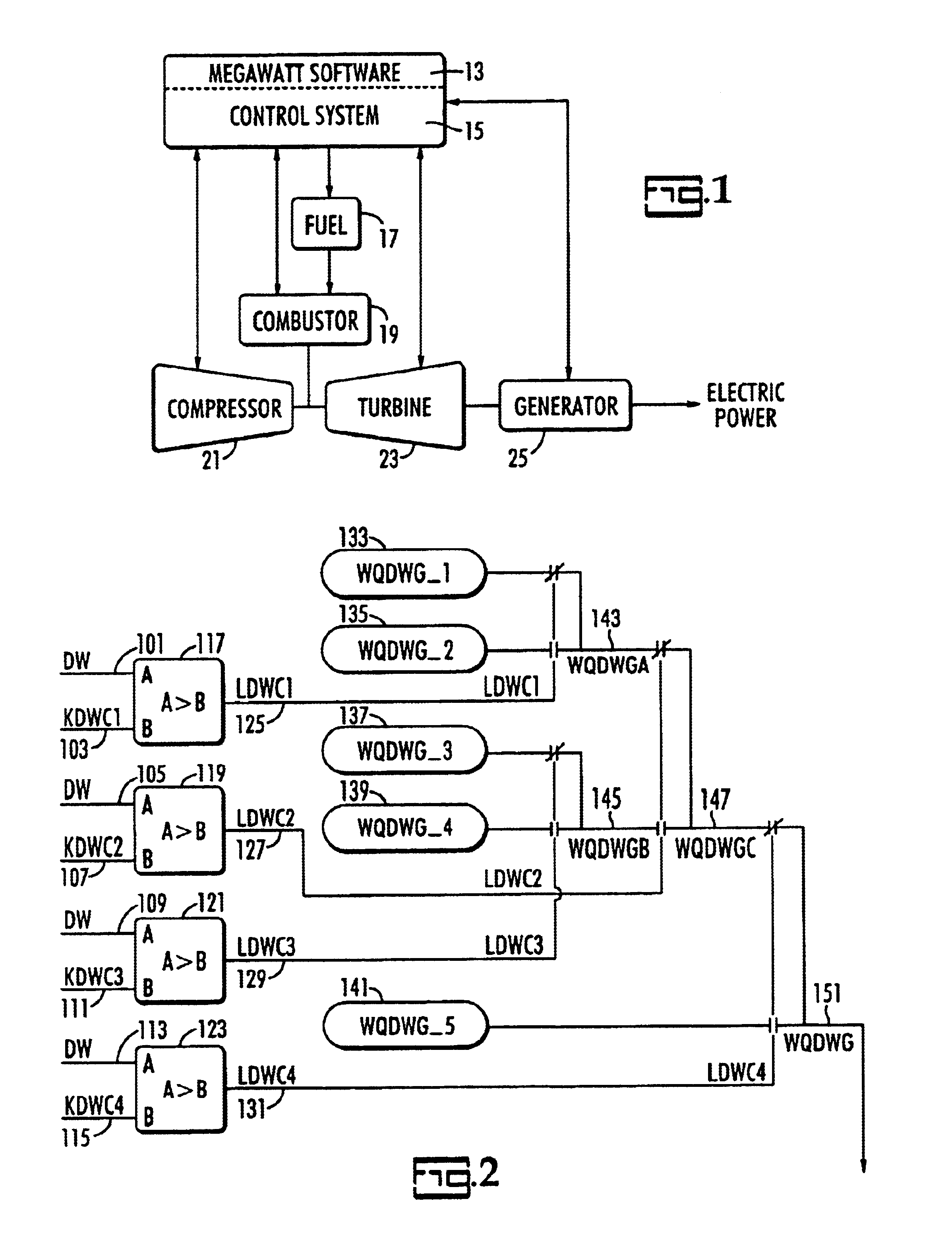
In accordance with this invention it has been found that a reliable process source, particularly the megawatt transducer, can be utilized for detecting and controlling out-of-compliance events as they relate to gas flow when being used for control of NOx and CO emissions through a water injection-based system. Various other advantages and features will become apparent from the following detailed description, together with reference to the figures.

The description and figures will utilize a mnemonic nomenclature typical as set forth in Gas Turbine Standard TM-30 and reproduced for clarity in the following Table:

TABLELetterGas Turbine OriginPhysical ParameterTypeAAirCurrent, AmperesBBearingVibrationCCompressorClearanceDDriven LoadDifferential PressureEElectricalFFuelFrequencyGGovernorStressHHertzIIntercoolerImpact PressJKCombustionConstantLLubeForceMExtractionsMiscellaneousNInlet Air NozzleSpeed0PStart Turn DeviceStatic PressureQ(Buffers)Volume or weightflowRRegeneratorReference, Contr...


PUM


Abstract

A computerized system for accurate, independent verification of natural gas fuel flow in order to control H2O injection flows. The H2O is injected into a combustion system to control emissions. The system comprises:receiving gas turbine control parameters from a gas turbine control system;receiving control parameters from a megawatt transducer;calculating values based upon readings from said control system and said megawatt transducer;comparing said values to a megawatt reference curve;detecting an abnormal reading;starting a timing sequence during which said reading is monitored;transferring NOx and H2O water injection control to a megawatt module at completion of said timing sequence;alerting operator said transfer;allowing for return of control to said gas turbine control system once said abnormal reading is corrected.

Description

FIELD OF THE INVENTIONThe present invention relates to a method for providing an independent verification of gas fuel flow which may be used to control water injection flows, which are used to control emissions from a natural gas power plant.BACKGROUND OF THE INVENTIONAs the demand for electricity skyrockets in the United States and the world, government and private industry must uncover and maximize power sources. One of these sources is natural gas.Origins of methane (CH4) include conversion of organic material by microorganisms (biogenesis), thermal decomposition of buried organic matter (thermogenesis), and deep crustal processes (abiogenesis). Buoyant methane migrates upward through rock pores and fractures and either accumulates under impermeable layers or eventually reaches the surface and dissipates into the atmosphere. Biogenic methane results from the decomposition of organic matter by methanogens, which are methane-producing micro-organisms and which pervade the near surf...

Claims


Application Information

Patent Timeline
IPC IPC(8): F02C3/20F02C3/30
CPCF02C3/30
Inventor WALKER, RONALD STEVEN
Owner WALKER RONALD STEVEN
Learn More