
Method and apparatus to increase combustion efficiency and to reduce exhaust gas pollutants from combustion of a fuel

a technology of combustion efficiency and combustion efficiency, which is applied in the direction of lighting and heating apparatus, combustion types, separation processes, etc., can solve the problems of incomplete combustion, inability to achieve the ideal environment in the real world, and health threats to residents in metropolitan areas around the world, so as to improve the combustion efficiency and enhance the combustion of fuels

Inactive Publication Date: 2005-02-08
RONNELL
View PDF22 Cites 207 Cited by
  • Summary
  • Abstract
  • Description
  • Claims
  • Application Information

AI Technical Summary

Benefits of technology

One object of the present invention is to provide a method and apparatus to enhance combustion of fuels to achieve more complete combustion thereby significantly improving combustion efficiency in internal combustion engines and external combustion processes.
Another object of the invention is to provide a method and apparatus to reduce the formation of exhaust pollutants due to more ideal and complete combustion conditions and to further combust any remaining pollutants as they exit the combustion process in the exhaust stream.
Another object of the invention is to make practical and economical changes to new and existing internal and external combustion and exhaust system configurations to save fuel and reduce world usage of petroleum and other combustion resources.
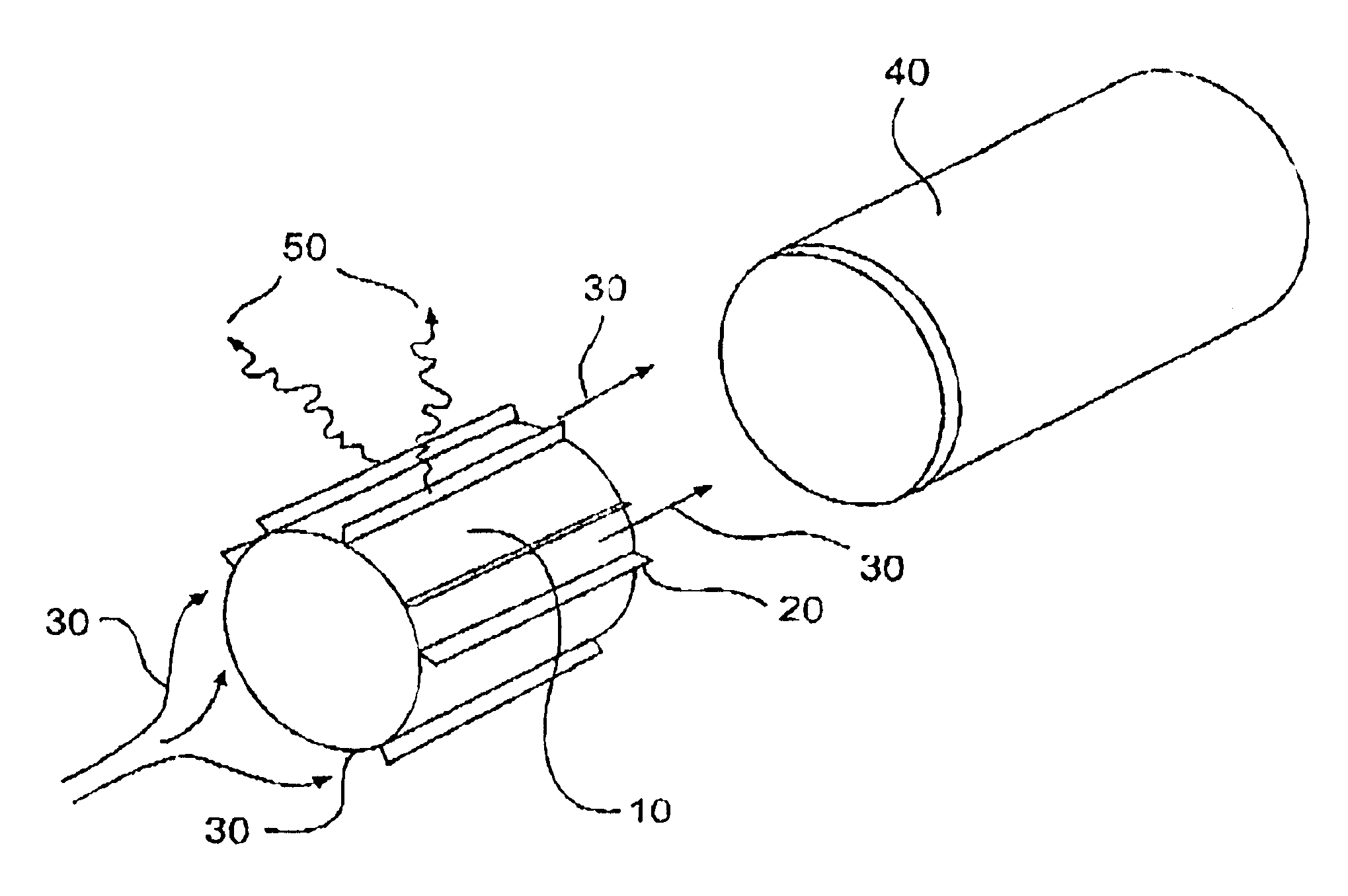
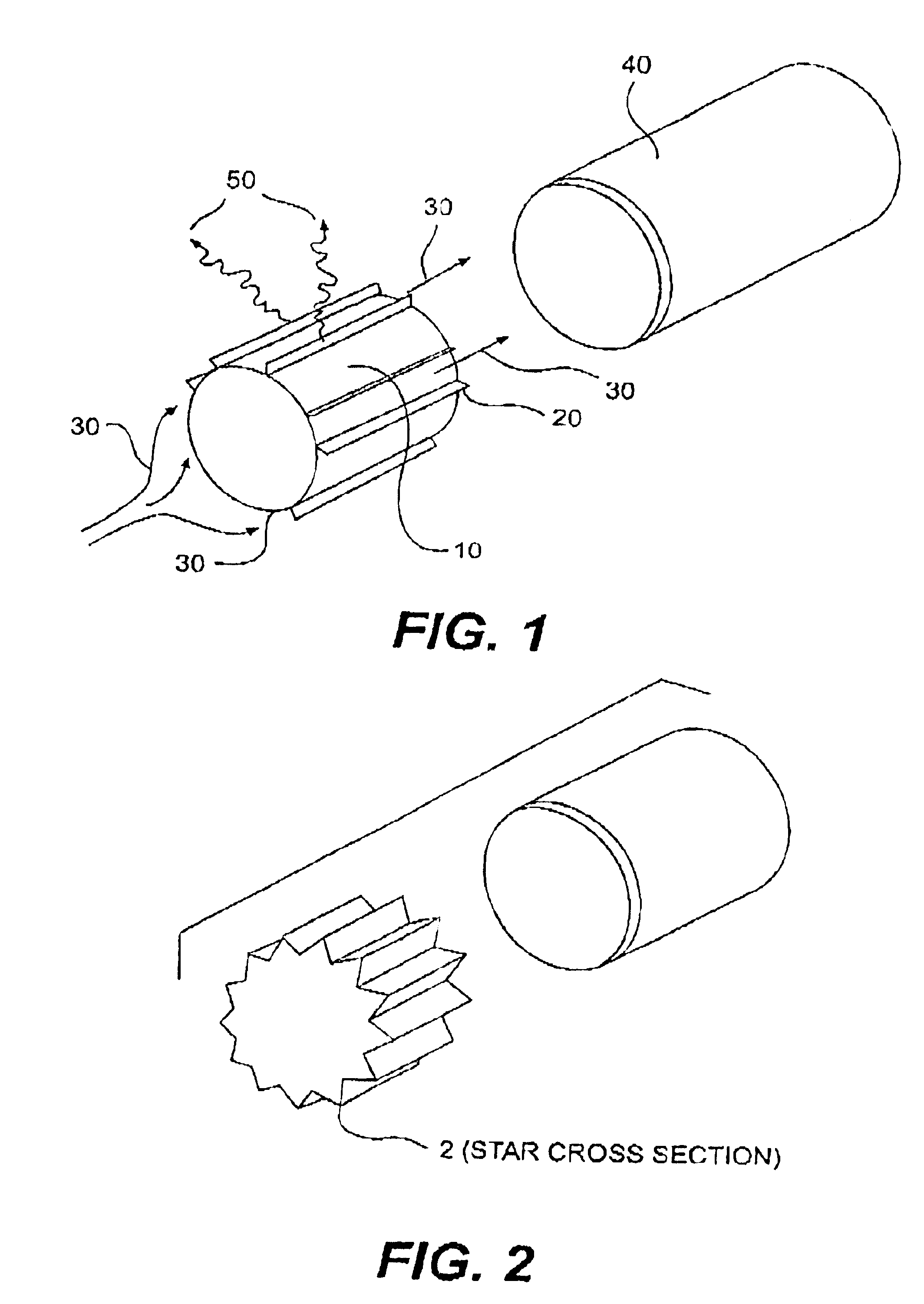
The fuel is treated to enhance combustion by placing a configuration having an electric field component and a magnetic field component just before or within the fluid feed section of the injector body. An improved fuel feed nozzle may be used to enhance combustion of the fuel. Said nozzle comprises both an electric field component and a magnetic field component.
The air is treated to enhance combustion by placing a configuration having an electric field component and a magnetic field component within the air stream conduit.

Problems solved by technology

A corresponding problem exists due to increasing pollutants being generated by internal combustion engines.
These pollutants threaten the health of residents in metropolitan areas throughout the world.
This ideal environment, however, cannot be achieved in the real world.
Real world conditions include incomplete combustion and less than ideal efficiencies of thermodynamic cycles.
The actual conditions that exist in internal combustion engines result in polluting exhaust products of unburned hydrocarbons, oxides of nitrogen (NOx), carbon monoxide and particulate matter.
The CI engine, however, has some serious drawbacks.
The smaller automobiles were also found to be less crash resistant resulting in more accident fatalities, especially when involved with a significantly larger and heavier vehicle.
Success in reducing pollutants at their source, the combustion zone, has been limited and the emphasis by manufacturers, government and academia researching this problem, has concentrated on the exhaust system.
One obvious disadvantage of preheating the fuel and / or fuel to air mixture, is the fact that less mass of combustibles will be transferred to the combustion chamber now that they are at higher temperatures.
This will result in a reduction in horsepower for the same displacement volume engine.
These patents claim that molecular fuel agglomerates are reduced and free radical and ionized fuel components are produced in the fuel thereby enhancing combustion resulting in increased fuel mileage and engine horsepower.
Following the successful development of the catalytic converter for the SI engine, the activities surrounding further exhaust treatment were limited.
The existing catalytic converter for the SI engine cannot be successfully used for the CI engine exhaust stream.
The sulfur component in the exhaust fouls the existing catalyst types and alternate catalyst development is underway, faced with a complex problem.
It is clear that a myriad of means to add energy or alter the combustion process has been put forth but is fragmented and not based on a sound unified theory explaining results.
Most of these fragmented solutions have not included practical, economic hardware devices for their implementation.

Method used


Image

  • Method and apparatus to increase combustion efficiency and to reduce exhaust gas pollutants from combustion of a fuel
  • Method and apparatus to increase combustion efficiency and to reduce exhaust gas pollutants from combustion of a fuel

Examples


Embodiment Construction

The Fuel Stream

The fuel is treated to enhance combustion by placing a configuration having an electric field component and a magnetic field component just before or within the fluid feed section of the injector body. Said configuration may be a single cylinder comprising two semi-circular segments of electric and magnetic field components, concentric cylinders of alternating electric and magnetic field components or a single cylinder having ail outer and inner side wherein said outer side is the electric field component and said inner side is the magnetic field component.

The electric field component may be an electret. Said electret may be a polymer and said polymer may be selected from the group consisting of polymethyl methacrylate, polyvinylchloride, polytetrafluoroethylene, polyethylene terafthalate, polystyrene, polyethylene, polypropylene, polycarbonate, polysuflone, polyamides, polymethylsiloxane, polyvinylfloride, polytrifluorochloroethylene, polyvinylidine fluoride epoxide ...


PUM

PropertyMeasurementUnit
combustionaaaaaaaaaa
electric fieldaaaaaaaaaa
magnetic fieldaaaaaaaaaa

Abstract

A method and apparatus is disclosed for increasing combustion efficiency in internal combustion engines and external combustors resulting in increased fuel economy and reduced exhaust pollutants. The same principles and apparatus of the invention are used in the exhaust stream to further reduce pollutants.

Description

FIELD OF THE INVENTIONThe present invention relates to a method and apparatus for enhancing combustion of fuels. More particularly, the present invention relates to a method and apparatus for enhancing combustion of fuels in an internal combustion engine or an external combustion device, to achieve increased fuel efficiency and concurrently reduce or eliminate pollutants generated due to incomplete combustion.BACKGROUNDThe increasing usage of the world's petroleum resources for combustion is rapidly depleting known reserves. A corresponding problem exists due to increasing pollutants being generated by internal combustion engines. These pollutants threaten the health of residents in metropolitan areas throughout the world. Legislation has been enacted to force automobile and truck manufacturers to control emissions and to increase engine efficiency. More legislation in this area is anticipated.The general conditions of combustion, especially regarding internal combustion engines, ar...

Claims


Application Information

Patent Timeline
Patent Type & Authority Patents(United States)
IPC IPC(8): F02M27/00F02M27/04F23D17/00F23K5/02F23K5/08F02B1/12F02B1/00
CPCF02M27/04F23K5/08F23D17/00F02B1/12F23C2202/30F23K2401/10F23K2301/101F23K2300/101F23K2400/10
Inventor TAMOL, SR., RONALD A.
Owner RONNELL
Learn More