
Heat sink including a heat dissipating fin and method for fixing the heat dissipating fin

a technology of heat dissipation fin and heat sink, which is applied in the direction of cooling/ventilation/heating modification, semiconductor/solid-state device details, semiconductor devices, etc., can solve the problems of reducing the strength of the heat dissipation fin, high processing cost, and softening of the fin

Inactive Publication Date: 2004-06-01
FURUKAWA ELECTRIC CO LTD +1
View PDF10 Cites 22 Cited by
  • Summary
  • Abstract
  • Description
  • Claims
  • Application Information

AI Technical Summary

Benefits of technology

This design provides a cost-effective, uniform heat transfer resistance and enhanced heat dissipation efficiency while maintaining the fin's strength, effectively addressing the limitations of existing methods.

Problems solved by technology

However, the above-mentioned conventional method for attaching the elongated folded fin to the heat transfer plate, block or the like has the following problems.
Namely, the method of joining the elongated folded fin to the heat transfer plate, block or the like by brazing or soldering, as well as the method of adhering the heat transfer plate, block or the like by the adhesive agent have a problem of its high processing cost.
Additionally, the method of joining the elongated folded fin to the heat transfer plate, block or the like by brazing or soldering has a problem that the fin is softened and the strength thereof is lowered by the heat in the joining process.
The method of fixing the elongated folded fin to the heat transfer plate, block or the like by caulking or screwing, as well as the method of adhering the elongated folded fin to the heat transfer plate, block or the like by the double-sided adhesive tape have a problem in which the heat transfer resistance (i.e, contact heat resistance) between the elongated folded fin and the heat transfer plate, block or the like becomes large.
Furthermore, the method of adhering the elongated folded fin to the heat transfer plate, block or the like by an adhesive agent has a problem in which the products thus processed do not have uniform heat transfer resistance, thus having a different quality in heat transfer resistance.

Method used


Image

  • Heat sink including a heat dissipating fin and method for fixing the heat dissipating fin
  • Heat sink including a heat dissipating fin and method for fixing the heat dissipating fin
  • Heat sink including a heat dissipating fin and method for fixing the heat dissipating fin

Examples


example 1

According to the present invention, a heat generating element (of 25 mm in length, 25 mm in width, 2 mm in height, and 15 W in heat generating rate) mounted on a circuit board (of 150 mm in length, 70 mm in width and 1.2 mm in thickness) of an electronic device was cooled by a heat sink including a heat dissipating fin comprising the following.

More specifically, as the base member in the heat sink, a shielding plate for electromagnetic shield (of 150 mm in length, 70 mm in width, 0.5 mm in thickness) which is made of aluminum A1050 was used.

As the heat dissipating fin, a folded (corrugated) fin made of aluminum A1050 in which the height of the mountain-shaped portions is 35 mm, the pitch of mountains is 4 mm, the depth is 20 mm, the number of mountains is 8, and the thickness of the fin plate is 0.4 mm was used.

As the fitting member, a heat receiving and heat transfer block made by an aluminum die casting process (of 90 mm in length, 45 mm in width and 4 mm in thickness) was used, a...

example 2

A heat sink including a heat dissipating fin was prepared by embedding a heat pipe of 3 mm in diameter and 90 mm in length in the fitting member used in the Example 1.

More specifically, an L-shaped groove of 2.9 mm in width, 2.9 in depth and 90 mm in length was formed in the middle portion of the fitting member, which was positioned 45 mm laterally from one end of the fitting member. The L-shaped groove was formed therein along the longitudinal direction of the heat dissipating fin.

The other components and a method for fabricating them were the same as those shown in Example 1.

A wind inside the apparatus was also the same as described in Example 1.

The heat sink including the above-mentioned heat pipe were operated to dissipate and cool the heat generated by the heat generating element, and the surface temperature of the heat generating element was measured. As a result, a temperature rise from the atmospheric temperature was 43.degree. C. and the heat resistance including the heat t...

example 3

According to the present invention, a heat generating element (of 25 mm in length, 25 mm in width, 2 mm in height, and 15 W in heat generating rate) mounted on a circuit board (of 150 mm in length, 70 mm in width and 1.2 mm in thickness) of an electronic device was cooled by a heat sink including a heat dissipating fin comprising the following.

More specifically, as the base member in the heat sink, a shielding plate for electromagnetic shield (of 150 mm in length, 70 mm in width, 0.5 mm in thickness) which is made of aluminum A1050 was used.

As the heat dissipating fin, a folded (corrugated) fin made of aluminum A1050 in which the height of the mountain-shaped portions is 35 mm, the pitch of mountains is 4 mm, the depth is 20 mm, the number of mountains is 8, and the thickness of the fin plate is 0.4 mm was used.

As the fitting member, a heat receiving and heat transfer block made by an aluminum die casting process (of 90 mm in length, 45 mm in width and 4 mm in thickness) was used, a...


PUM


Abstract

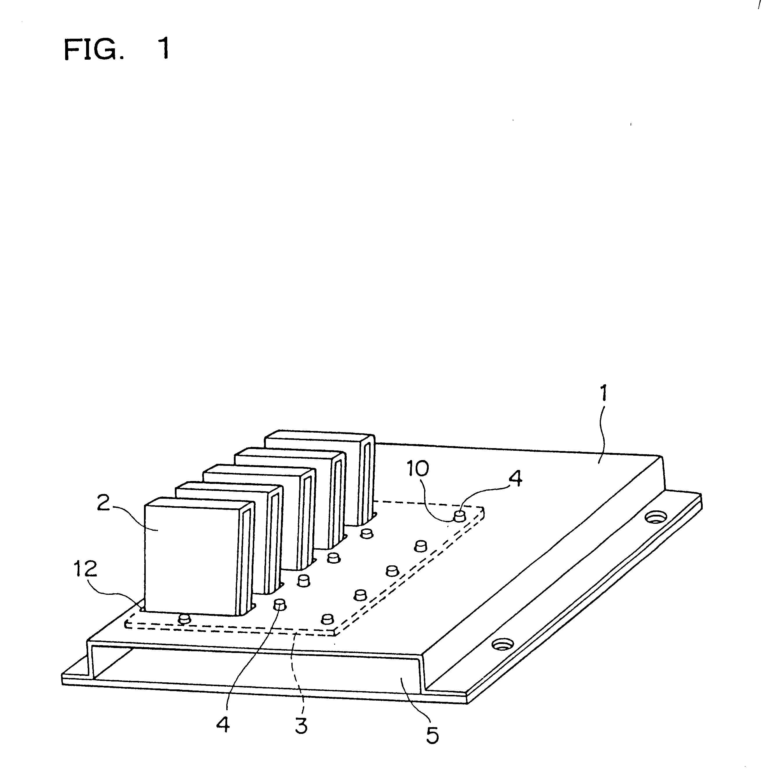
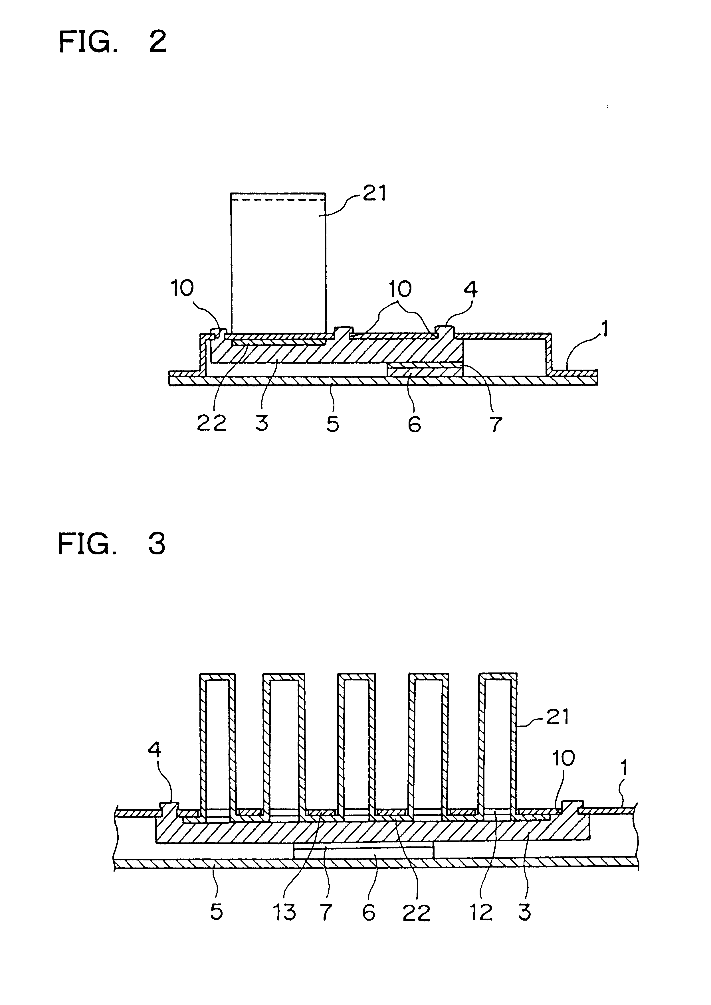
A heat sink including a heat dissipating fin comprises (1) a heat dissipating fin having a plurality of mountain-shaped portions and base portions supporting the mountain-shaped portions, (2) a base member having a plurality of slits into which the mountain-shaped portions of the heat dissipating fin are to be inserted and a plurality of holes for fixing the heat dissipating fin, and (3) a fitting member, provided with a plurality of projecting portions corresponding to the plurality of holes of the base member, for fixing the heat dissipating fin between the base member and the fitting member itself.

Description

1. Field of the InventionThe present invention relates to a heat sink including a heat dissipating fin and a method for fixing the heat dissipating fin to the heat sink main body. A heat sink including a heat dissipating fin according to the present invention may be utilized not only for heat dissipating and cooling of a heat generating electronic component or the like used in an electronic device but also for heat dissipating and cooling of articles in any field which require heat dissipation.2. Related ArtA semiconductor chip or the like used in various electronic devices such as a personal computer, a game console, an audio system or the like has been made smaller in size, and larger in integration density to remarkably improve processing speed, and therewith heat generating density thereof becomes much larger.Various corrugated fins such as those comprising sequentially connected elongate U shaped parts (hereinafter referred to as "elongated folded fin") are widely used as a mea...

Claims


Application Information

Patent Timeline
Patent Type & Authority Patents(United States)
IPC IPC(8): H01L23/40H01L23/367H01L23/34
CPCH01L23/3672H01L23/4006H01L2023/4056H01L2023/4081H01L2023/4087H01L2924/0002H01L2924/00
Inventor SASAKI, CHIYOSHISOTANI, JUNJIOHMI, MASARUHAMA, TOSHIKATSUOOTORI, YASUHIRO
Owner FURUKAWA ELECTRIC CO LTD
Learn More