Porous cubic boron nitride based material suitable for subsequent production of cutting tools and method for its production

a cubic boron nitride and cutting tool technology, applied in the direction of magnetic/electric field screening, metal-working apparatus, turning machine accessories, etc., can solve the problems of large cost reduction per cutting edge, manual packing of powder mixture containing pcbn into the groove in principle, and relatively expensive tools to produ

Inactive Publication Date: 2004-01-13
SANDVIK INTELLECTUAL PROPERTY AB
View PDF13 Cites 21 Cited by
  • Summary
  • Abstract
  • Description
  • Claims
  • Application Information

AI Technical Summary

Problems solved by technology

The tools are relatively expensive to produce due to the many steps the product must undergo before it is finished.
Although the method described leads to extensive cost reductions per cutting edge, it has one major drawback in that the packing of a powder mixture containing PcBN into the grooves in principle must be done manually.
The poor flow properties of PcBN powder in combination with the required groove geometry make automatic processing unreliable.
Apart from obvious health hazards, manual packing may lead to uneven packing density and to excessive oxygen exposure of the PcBN powder.
Careful control of the oxygen content in the PcBN powder is critical for the HP / HT sintering since excessive oxygen negatively affects the consolidation process.

Method used


Image

  • Porous cubic boron nitride based material suitable for subsequent production of cutting tools and method for its production
  • Porous cubic boron nitride based material suitable for subsequent production of cutting tools and method for its production

Examples


example

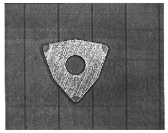
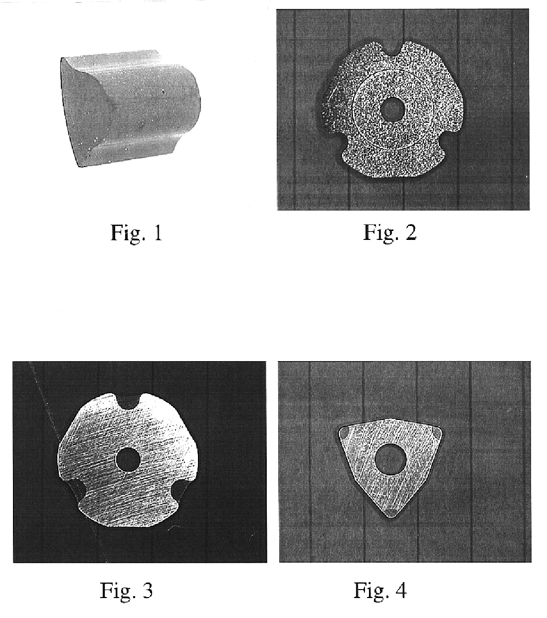
A cutting tool insert according to U.S. Pat. No. 5,676,496 was made according to the present invention. 57 wt % cBN, 35 wt % Ti(C.sub.0.5,N.sub.0.5) and 8 wt % Co.sub.2 Al.sub.9 was first attritor-milled for 60 minutes using cemented carbide milling bodies to obtain a homogeneous powder mixture. 6.5% polyethylene glycol, PEG, was then added and the powder mixed in ethanol to a homogeneous slurry. The slurry was dried using the spray drying technique to a powder with an average agglomerate size of about 100 .mu.m and good flow properties. The powder was pressed to a body with desired dimensions using conventional tool pressing technology. The pressing was done at the highest possible compaction pressure without jeopardizing the press tool in order to obtain a high green body density. The pressing agent was removed from the green bodies at 200-320.degree. C. in flowing hydrogen. The temperature was increased to 1050.degree. C. at 10.degree. C. / min in vacuum and then further increased ...


PUM

PropertyMeasurementUnit
temperatureaaaaaaaaaa
diameteraaaaaaaaaa
diameteraaaaaaaaaa

Abstract

The presently claimed invention relates to a method of making a PcBN cutting tool insert. The method includes the following steps:mixing raw material powders, (e.g., cBN, hBN, TiC, TiN, Ti(C,N), WC, W, C, Co, Co2Al9, Al AlN, Al2O3) with a liquid (e.g., ethanol) and an agent (e.g., polyethylene glycol, PEG) to form a homogeneous slurry with the desired composition;forming spherical powder agglomerates, typically 100 mum in diameter, preferably by spray drying;pressing said agglomerates to form a body of desired dimensions and density using conventional tool pressing technology;removing the agent from the powder at a suitable temperature and atmosphere;raising the temperature to 1000-1350° C. in vacuum;solid state sintering the body at 1000-1350° C. in vacuum, for 1-90 minutes to form a body with 35-55 vol % porosity;optionally, adding 0.5-1000 mbar of nitrogen to the sintering atmosphere at the hold time or during cooling; andHP / HT treating the porous body to form a dense body of desired shape and dimension.

Description

The present invention relates to a method of making tools with cutting edges formed of polycrystalline cubic boron nitride (PcBN) which are bonded to a body of cemented carbide or cermet.Cutting tools having cutting edges formed of a super hard abrasive such as a cubic boron nitride (cBN)-based material are manufactured by powder metallurgical techniques and are mainly used for the machining of cast iron and hardened steel. For cast iron, a tough material with 80-100 wt % cBN is used, while for hardened steel 10-50 wt % of TiC, TiN or Ti(C,N) is usually added. This addition decreases toughness, but greatly improves the chemical stability of the material. Most often, the PcBN (polycrystalline cubic Boron Nitride) material also contains smaller amounts (typically <10 wt % each with a total maximum content of all such materials being 25 wt %) of other components, e.g., Co, Ni, WC, Al, AlN and Al.sub.2 O.sub.3. These are either added to the raw material powder or obtained during proc...

Claims


Application Information

Patent Timeline
Patent Type & Authority Patents(United States)
IPC IPC(8): C22C1/05C22C26/00H01R13/648H01R13/658B22F3/11B22F7/00B22F7/06B22F7/08B23B27/14B23P15/28C22C29/14H01R9/03H01R13/58H05K9/00
CPCC22C1/051C22C26/00H01R13/648C22C29/16B22F7/06B22F9/026B22F3/101B22F3/1017B22F3/14B22F2005/001B22F2998/00B22F2998/10B22F2999/00B22F2201/20B22F2201/02
Inventor ROLANDER, ULFWEINL, GEROLD
Owner SANDVIK INTELLECTUAL PROPERTY AB
Why Eureka
Try Eureka