Probe for use in an infrared thermometer
a technology for infrared thermometers and probes, which is applied in the direction of optical radiation measurement, instruments, applications, etc., can solve the problems of substantial large heat conducting blocks, inability to accurately measure erros, and thermal coupling arrangement comprising fives parts
- Summary
- Abstract
- Description
- Claims
- Application Information
AI Technical Summary
Benefits of technology
Problems solved by technology
Method used
Image
Examples
first embodiment
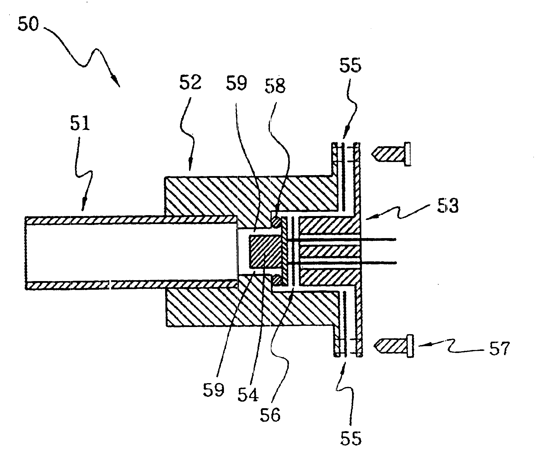
FIG. 5 shows probe 50 of an infrared thermometer according to the present invention. Probe 50 comprises waveguide 51, first heat sink 52, second heat sink 53, IR sensor 54, O-ring, 58, first silicon film 55 and second silicon film 56. Waveguide 51 directs the thermal radiation emitted from the eardrum and nearby tissues to IR sensor 54 and generates corresponding electronic signals. IR sensor 54 outputs electronic signals to a calculating circuit (not shown in the drawings) for showing the human body temperature. First heat sink 52 is thermally coupled to a waveguide 51 for reducing the temperature variation of waveguide 51. If the surface of waveguide 51 is coated with a layer of gold with high reflectivity, the thermal mass of first head sink 52 could be relatively reduced. Second heat sink 53 is thermally coupled to IR sensor 54 for reducing the temperature variation of IR sensor 54.
For obtaining a better effect of the heat dissipation, first heat sink 52 and second heat sink 53 ...
second embodiment
FIG. 7 shows probe 70 of an infrared thermometer according to the present invention. The difference from probe 50 of the infrared thermometer shown in FIG. 5 is that probe 70 does not have first silicon film 55 and second silicon film 56. For achieving the purpose of raising the time constant of thermistor 24 to approach that of the cold junction of thermopile chip 23, the present invention changes the internal structure of IR sensor 71 as shown in FIG. 8.
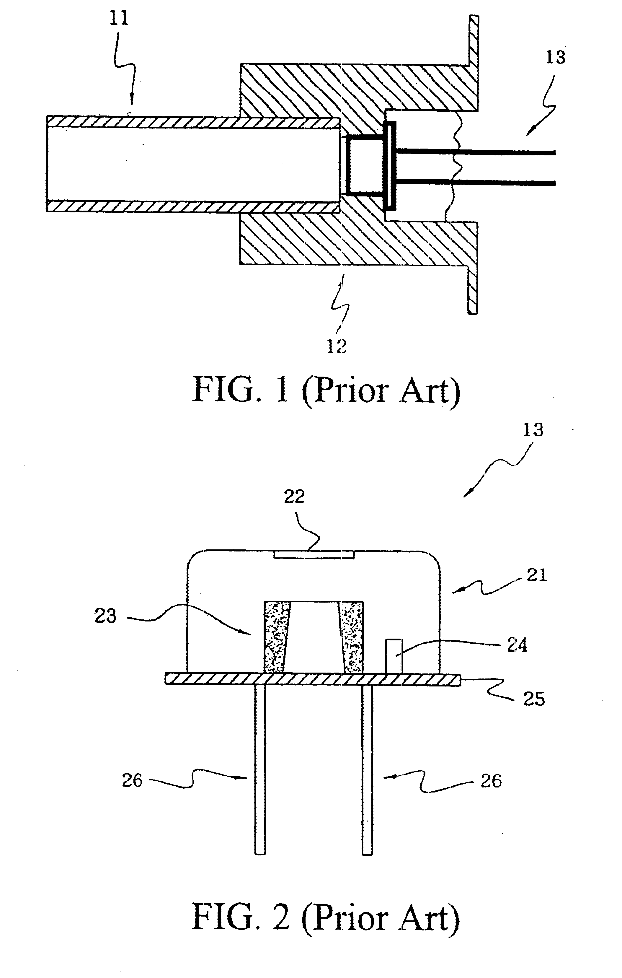
FIG. 8 shows an IR sensor according to the present invention. The difference from IR sensor 13 shown in FIG. 2 is that substrate 87 with less thermal conductivity (such as a silicon substrate) is positioned between thermistor 84 and base plate 85 of IR sensor 71 to increase the thermal resistance effect of the equivalent model. Like the first embodiment of the present invention, base plate 85 is thermally coupled to second heat sink 53.
FIG. 9 shows an equivalent model of probe 70 shown in FIG. 7 responding to the temperature, where...
PUM
 Abstract
Description
Claims
Application Information
 - R&D
- Intellectual Property
- Life Sciences
- Materials
- Tech Scout
- Unparalleled Data Quality
- Higher Quality Content
- 60% Fewer Hallucinations
Browse by: Latest US Patents, China's latest patents, Technical Efficacy Thesaurus, Application Domain, Technology Topic, Popular Technical Reports.
© 2025 PatSnap. All rights reserved.Legal|Privacy policy|Modern Slavery Act Transparency Statement|Sitemap|About US| Contact US: help@patsnap.com


