Eureka AIR delivers breakthrough ideas for toughest innovation challenges, trusted by R&D personnel around the world.

Process and apparatus for forming plastic sheet

a technology of plastic sheet and process, applied in the field of optical storage medium, can solve the problems of low density, flexibility and impact resistance, low mechanical properties of materials, and difficulty in producing plastic sheet with the requisite optical specifications needed for use in optical and display applications at reasonable costs, and achieves the effects of reducing surface roughness, reducing birefringence, and reducing cos

Inactive Publication Date: 2002-09-17
ROHM & HAAS CO
View PDF33 Cites 8 Cited by
  • Summary
  • Abstract
  • Description
  • Claims
  • Application Information

AI Technical Summary

Benefits of technology

Compact discs ("CD") and digital versatile discs ("DVD") contain information encoded as pits and grooves on a polymer substrate. The sequence and length of pits encode information which is read with a focused laser beam through the substrate. In the typical manufacture of compact discs, the pits and grooves are replicated from a stamper in a mold onto the substrate. Once the substrate has been molded, it is then metallized by the deposition of a thin layer of reflective material, such as aluminum or gold. The substrate may then optionally be coated with a lacquer or resin to which ink may be applied, such as to provide a label. Advances in optical data storage require the encoding of increased amounts of information, which decreases the spacing between the pits and grooves. In order to prevent errors in the reading of such closely packed information (that is, high density), it is important that the substrate be of a sufficiently high quality that it does not deform around the pits and grooves during manufacture or writing, in the case of writeable discs. Such deformations cause errors in the reading of the encoded information. An advantage of the present invention is that the high quality optical plastic sheet produced has lower birefringence, lower surface roughness and higher dimensional stability than known injection molded substrates. This allows for a higher density of encoded information with very little deformation around the pits and grooves, provides for the writing and reading of encoded information without optical distortion, and gives greater signal to noise ratios.
is that the high quality optical plastic sheet produced has lower birefringence, lower surface roughness and higher dimensional stability than known injection molded substrates. This allows for a higher density of encoded information with very little deformation around the pits and grooves, provides for the writing and reading of encoded information without optical distortion, and gives greater signal to noise ratios.
DVD's are generally produced in the same way as compact discs, but may further have an added semireflective layer and polymer layer to encode one or more additional layers of information on top of the first (replicated) surface. Also, DVD's may have two or more discs bonded together with a transparent adhesive to increase the information content. Typically, DVDs comprise two to four layers.
When the sheet of the present invention is used as a substrate in an optical storage medium, the optical storage medium comprises a) a high quality plastic sheet produced by the present method; b) a reflective or semireflective layer disposed on at least one side of the sheet; and optionally c) a protective layer disposed on at least one side of the sheet. The reflective or semireflective layer may be formed from any reflective or semireflective material. When a reflective layer is used, it is preferred that the reflective layer comprise a metal, such as aluminum or gold. Such reflective layer is typically applied to the substrate by sputtering or vacuum deposition. When a semireflective layer is used, it is preferred that the semireflective layer comprises a metal. Suitable metals for use in semireflective layers include, but are not limited to gold, aluminum, and metal alloys, such as aluminum alloys, When metals are used as the semireflective layer, only a very thin layer of the metal is required. The protective layer may be any coating applied to the plastic substrate or reflective layer that does not interfere with the desired optical properties. It is preferred that the protective layer is a lacquer or resin. It is further preferred that the plastic substrate is selected from the group consisting of homopolymers and copolymers of polycarbonate, polystyrene, polyacrylic, polyester, polyolefin, polyacrylate, and mixtures thereof.
Information may be encoded on optical storage media comprising the sheet of the present invention by any known means, such as embossing or imaging. For example, optical storage media may be prepared by hot embossing processes, such as those described in M. T. Gale, Micro-Optics, (Ed . H. P. Herzig), Taylor & Francis, London, UK, chapter 6, (1997). Hot embossing uses a heated stamper to encode information on the substrate. The hot stamper may be used in a continuous process (roll to roll) or in a discrete process, such as compression molding. In the alternative, the substrate may first be coated with a thin polymer film prior to embossing. Suitable polymer films include, but are not limited to: latexes, photopolymers, and ultraviolet curable resins. The thickness of tile polymer coating is generally 0.05 to 10 microns, and preferably 0.1 to 1 microns. Such a polymer film results in faster embossing with better replication of the encoded information.
In the alternative, a photopolymer may be used to encode information on optical storage media. When a photopolymer is used, it is first coated on the substrate. The coated substrate is then imaged using any lithographic process known in the art, such as those used in the semiconductor industry.

Problems solved by technology

Glass or quartz sheets have been used in display applications because these materials are able to meet the optical and flatness requirements and have good thermal and chemical resistance and barrier properties; however, these materials do not have some of the desired mechanical properties, most notably low density, flexibility and impact resistance.
Although plastic sheets have greater flexibility, are more resistant to breakage, and are of lighter weight than glass or quartz sheets of equal thickness, it has been very difficult to produce plastic sheet having the requisite optical specifications needed for use in optical and display applications at reasonable costs.
Moreover, many types of plastic sheet undergo unacceptable dimensional distortion when subjected to substrate processing conditions during manufacture of the display devices, particularly with respect to temperature.
Of these methods, several are not suitable for producing high quality plastic sheet.
For example, injection molding is likely to produce high amounts of polymer chain orientation, especially for thin sheets (i.e., 1 mm thickness or less), due to the flow of molten plastic into the mold, which unacceptably increases birefringence for polymers with non-negligible photoelasticity (stress optic) coefficients.
However, even with these improvements, injection compression molding has limited ability to produce high quality sheet.
Compression molding and press polishing may be used to produce sheets with good surface quality; however, the squeezing flow inherent in such processes results in polymer chain orientation which results in unacceptable shrinkage during thermal cycling.
Moreover, these processes are not continuously operable and therefore increase labor and production costs.
Stretching operations (for example, for the production of uniaxially- or biaxially-oriented films) and blown film extrusion inherently introduce large amounts of polymer chain orientation and are unsuited for the production of high quality plastic sheet.
Solvent casting can be used to produce high quality film; however, there are practical limitations to the maximum film thickness which can be produced by this method.
Sheet extrusion is run as a continuous operation, but this process introduces unacceptable polymer chain orientation due to the nature of the polymer flow in the die and between the polished rollers in the roll stack.

Method used

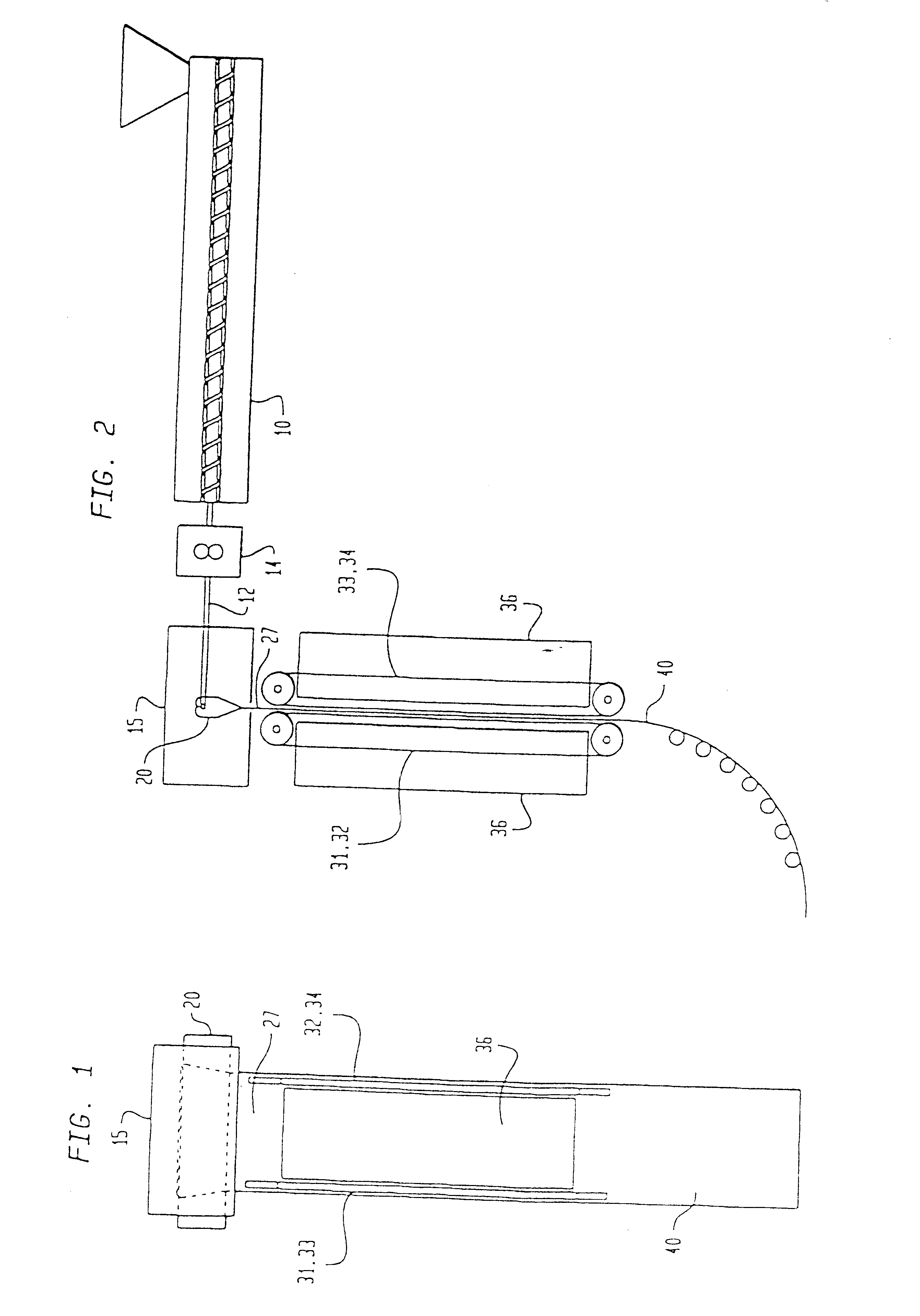
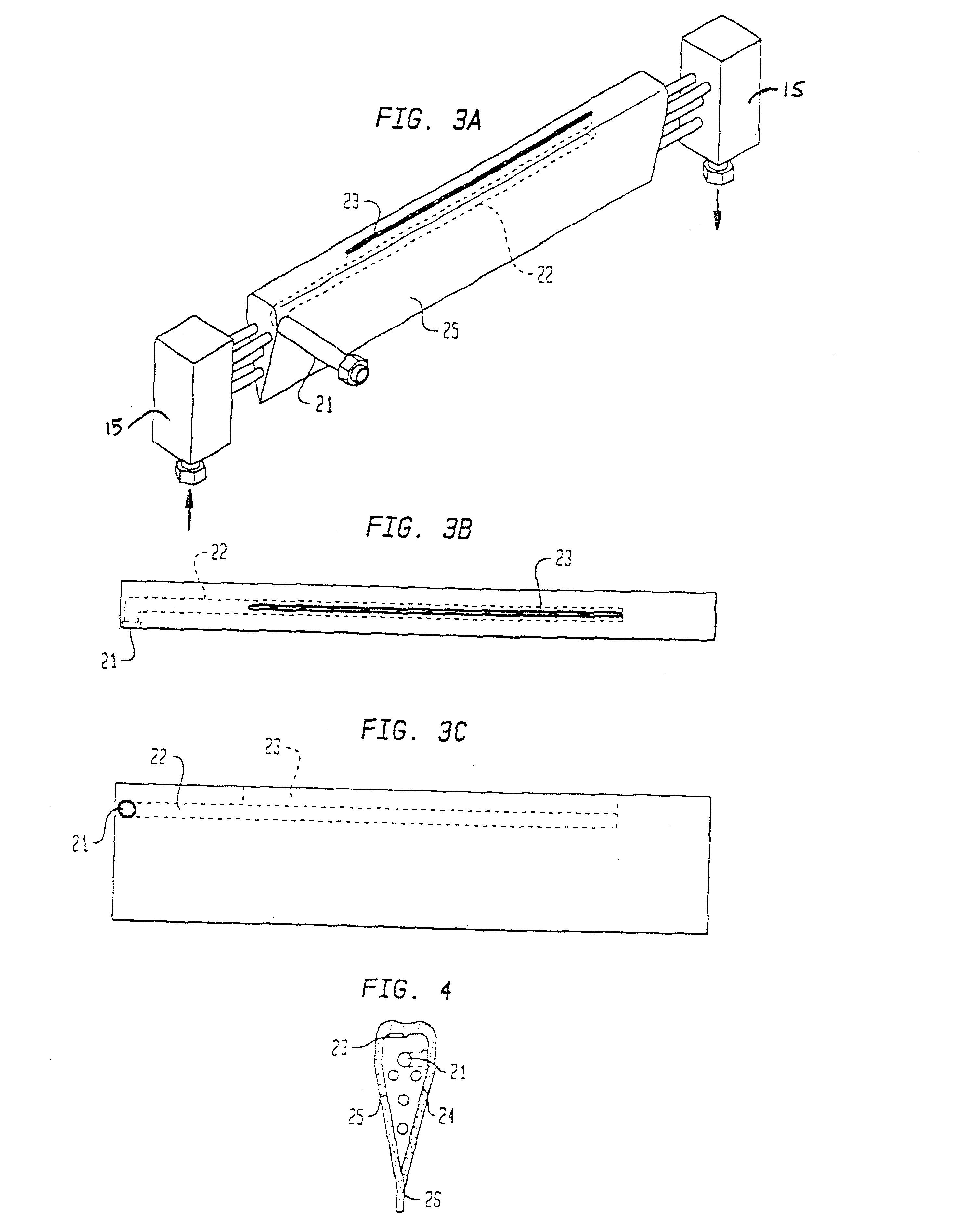

Image

  • Process and apparatus for forming plastic sheet
  • Process and apparatus for forming plastic sheet
  • Process and apparatus for forming plastic sheet

Examples


example 2

Preparation of Imidized Acrylic Sheet

This example illustrates the method of the present invention used to produce optical quality imidized acrylic sheet.

A capped imidized acrylic resin having an weight average molecular weight of 108,000 and a glass transition temperature of about 180.degree. C. was starve-fed into a 2 inch (5 cm) diameter single screw vented two-stage extruder having a 30:1 L:D ratio at a rate of 2.5 g / s using a gravimetric feeder. The extruder barrel had a temperature profile from 246.degree. C. at the feed end to 329.degree. C. at the discharge end. The resin was devolatilized using a devolatilization vent operating at 720-750 mm Hg. The screw was rotated at 30 rpm. A gear-type melt pump was used to pump the molten resin through a screen pack filter to a 25.5 inch (65 cm) long overflow die with a 1.588 cm diameter internal conduit and a 16 inch (40 cm) long slot tapering from 0.038 to 0.042 inch (0.965 to 1.067 mm). The melt pump temperature was 329.degree. C. Th...

example 3

Preparation of Polycarbonate Sheet

This example illustrates the method of the present invention used to produce optical quality polycarbonate sheet.

Extrusion-grade polycarbonate resin (Lexan 101, GE Plastics, Pittsfield, Mass.) was starve-fed into a 2 inch (5 cm) diameter single screw vented two-stage extruder having a 30:1 L:D ratio at a rate of 4.4 g / s using a gravimetric feeder. The extruder barrel had a temperature profile from 232.degree. C. at the feed end to 315.degree. C. at the discharge end. The resin was devolatilized using a devolatilization vent operating at 720-750 mm Hg. The screw was rotated at 30 rpm. A gear-type melt pump was used to pump the molten resin through a screen pack filter to a 37.5 inch (95 cm) long overflow die with a 1.905 cm diameter internal conduit and a 28 inch (71 cm) long slot tapering from 0.038 to 0.045 inch (0.965 to 1.143. mm). The melt pump temperature was 315.degree. C. The melt pump suction pressure was approximately 3400 kPa. The melt pum...

example 4

Preparation of Polycarbonate Film

This example illustrates the method of the present invention used to produce optical quality polycarbonate film.

Extrusion-grade polycarbonate resin (Lexan 101, GE Plastics, Pittsfield, Mass.) was starve-fed into a 2 inch (5 cm) diameter single screw vented two-stage extruder having a 30:1 L:D ratio at a rate of 2.5 g / s using a gravimetric feeder. The extruder barrel had a temperature profile from 232.degree. C. at the feed end to 315.degree. C. at the discharge end. The resin was devolatilized using a devolatilization vent operating at 720-750 mm Hg. The screw was rotated at 30 rpm. A gear-type melt pump was used to pump the molten resin through a screen pack filter to a 37.5 inch (95 cm) long overflow die with a 1.905 cm diameter internal conduit and a 28 inch (71 cm) long slot tapering from 0.038 to 0.045 inch (0.965 to 1.143 mm). The melt pump temperature was 315.degree. C. The melt pump suction pressure was approximately 3400 kPa. The melt pump d...


PUM

PropertyMeasurementUnit
shrinkageaaaaaaaaaa
roughnessaaaaaaaaaa
roughnessaaaaaaaaaa

Abstract

Disclosed is an apparatus for formation of high quality plastic sheet in a continuous fashion. Also disclosed are a variety of optical and electronic display applications for high quality plastic sheet produced in a continuous fashion.

Description

The present invention relates to a process and apparatus for forming plastic sheet. In particular, the present invention relates to a process and apparatus for forming plastic sheet having low residual stress and high surface quality. Plastic sheet formed according to the process of the present invention is particularly useful in optical and electronic display applications, such as, for example, optical windows, optical filters, recording media, and liquid crystal displays ("LCD").Sheets of optical quality glass or quartz are used in electronic display applications as "substrates." In such applications, a "substrate" is a sheet of material used to build an electronic display. Such substrates can be transparent, translucent or opaque, but are typically transparent. In general, such sheets have conductive coatings applied thereto prior to use as substrates. Such substrates often have stringent specifications for optical clarity, flatness and minimal birefringence, and typically must h...

Claims


Application Information

Patent Timeline
Patent Type & Authority Patents(United States)
IPC IPC(8): B29C47/08B29C47/50B29C47/88B29C47/34B29C47/38B29C47/14B29C47/58B29C47/68B29C48/08B29C48/305B29C48/355B29C48/38B29D7/01B29K101/12B29L7/00
CPCB29C47/0021B29C47/14B29C47/34B29C47/367B29C47/884B29C47/885B29C47/38B29C47/364Y10T428/21B29C47/0033B29C47/683B29L2017/00Y10S428/913Y10S430/146Y10T428/1086Y10T428/10B29C47/003B29C48/08B29C48/12B29C48/13B29C48/305B29C48/355B29C48/37B29C48/387B29C48/395B29C48/6914B29C48/9135B29C48/9145B29C48/919Y10T428/31678Y10T428/31507C09K2323/00C09K2323/06B29D7/01
Inventor DAECHER, JEFFREY LAWRENCEFIELDS, STEVEN DAVIDKHANARIAN, GAROSTEIN, ALAN DANIEL
Owner ROHM & HAAS CO
Why Eureka
Eureka Blog
Learn More