
Ceramic wiring board

a wiring board and ceramic technology, applied in the direction of ceramic layered products, semiconductor/solid-state device details, transportation and packaging, etc., can solve the problems of difficult to reduce the size and drive up the mounting cost, perovskite dielectric, and cannot be co-fired with glass ceramics, so as to reduce the difference in the coefficient of thermal expansion, and easy laminate

Inactive Publication Date: 2002-09-10
KYOCERA CORP
View PDF5 Cites 25 Cited by
  • Summary
  • Abstract
  • Description
  • Claims
  • Application Information

AI Technical Summary

Benefits of technology

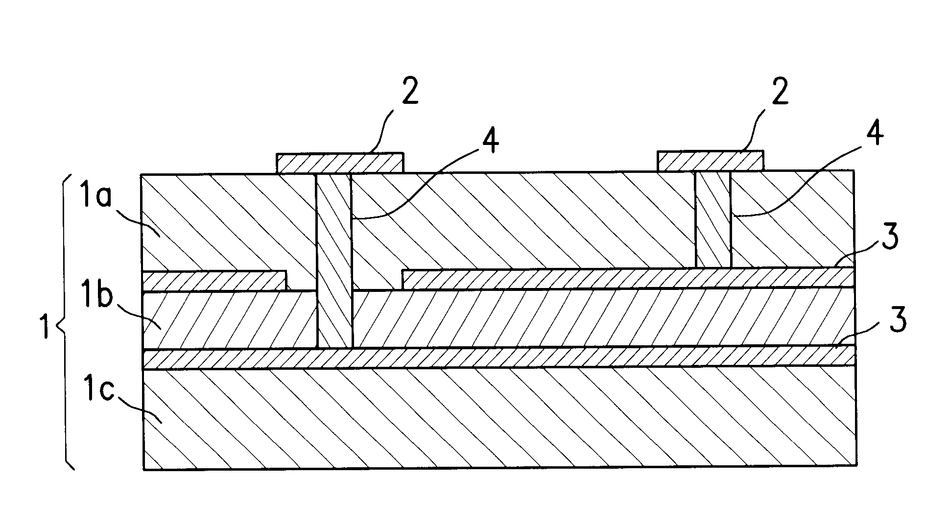
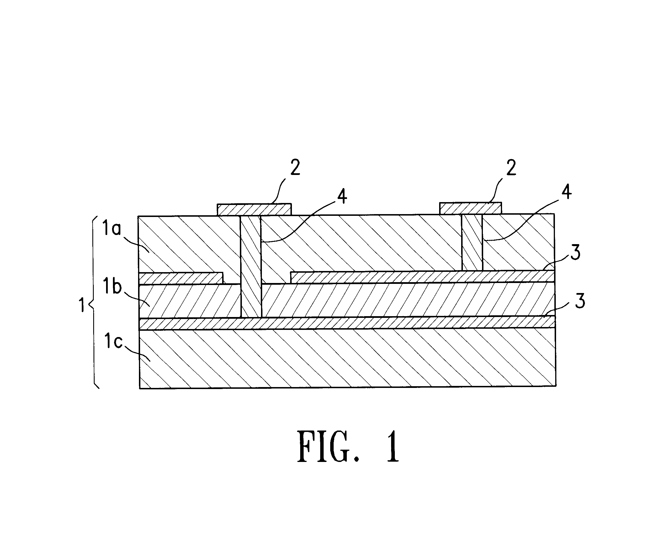
Further the ceramic sintered product forming the high dielectric layer can be co-fired with the conventional glass ceramic sintered product of a high thermal expansion, and can be easily laminated on the insulating layer of the glass ceramic sintered product of a high thermal expansion. Accordingly, the ceramic wiring board of the invention can assume various laminated layer structures. For instance, the high dielectric layer is laminated on a glass ceramic insulating layer of a low dielectric constant and of a high thermal expansion so as to be incorporated in the insulating substrate, in order to further decrease the difference in the coefficient of thermal expansion from the external circuit board. Besides, the ceramic wiring board having such a laminated layer structure is of a structure that contains the capacitor. By arranging the high dielectric layer between a pair of electrode layers, therefore, an electrostatic capacity as a capacitor can be drawn out, eliminating the need of mounting such parts to capacitor devices and offering a great advantage from the standpoint of realizing the electronic device as a whole inclusive of the wiring board in a small size.

Problems solved by technology

So far, however, the ceramics wiring hoard, capacitor devices and resistor devices have been separately mounted on an external circuit board, making it difficult to decrease the size and driving up the cost for mounting.
However, a composite perovskite dielectric material comprising chiefly BaO--TiO.sub.2 or PbO--TiO.sub.2 which has been known as ceramics having a high dielectric constant, cannot be co-fired with the glass ceramics, and is not suited for the production of a ceramic wiring board having a large coefficient of thermal expansion.
Thus, it is very difficult to produce the ceramic wiring board having a small difference of thermal expansion from the external circuit board such as printed board, by using the composite perovskite dielectric material.
With the sintered product of the glass ceramics, therefore, the sintering is greatly impaired depending upon the filler component such as BaTiO.sub.3 or CaTiO.sub.3, making it difficult to obtain a densely sintered product at low temperatures and hindering the effort for realizing the practical use.

Method used


Image

  • Ceramic wiring board
  • Ceramic wiring board

Examples


experiment 1-- 1

(Experiment 1--1)

A glass powder (yield point of 700.degree. C., coefficient of thermal expansion of 6.5.times.10.sup.-6 / .degree. C., Pb amount of not larger than 50 ppm) comprising 41% by weight of SiO.sub.2 --37% by weight of BaO--10% by weight of B.sub.2 O.sub.3 --7% by weight of Al.sub.2 O.sub.3 --5% by weight of CaO was prepared, and filer powders shown in Table 1 were prepared. In Table 1, the coefficients of thermal expansion are those at 40 to 400.degree. C.

The fillers of Table 1 were each weighed by 50% by volume and were added to 50% by volume of the glass powder, followed by the addition of a solvent, and were then pulverized and mixed by using a ball mill. Thereafter, an organic binder and a plasticizer were added and mixed to a sufficient degree to prepare slurries from which green sheets having a thickness of 500 .mu.m were prepared by the doctor blade method.

Samples measuring 50 mm.times.50 mm were cut out from the thus obtained green sheets, were pressed, and from wh...

experiment 1-2

(Experiment 1-2)

Sintered products (samples Nos. 10 to 37) were prepared in the same manner as in Experiment 1--1 but changing the composition ratio of lanthanum titanate and glass as shown in Tables 2 to 5, and their properties were evaluated. The results were as shown in Tables 2 to 5.

TABLE 2 No. 10 11 12 13 14 15 16 Glass (vol. %) 30 35 40 45 55 60 70 La.sub.2 O.sub.3 --2TiO.sub.2 70 65 60 55 45 40 30 (vol. %) Porosity (%) 12.4 0.5 0.42 0.43 0.15 0.05 0.03 Coefficient of thermal -- 12.0 11.6 11.2 10.3 10.0 9.5 expansion (x10.sup.-6 / .degree. C.) Dielectric constant -- 22.9 21.3 18.9 15.5 14.1 9.5

TABLE 2 No. 10 11 12 13 14 15 16 Glass (vol. %) 30 35 40 45 55 60 70 La.sub.2 O.sub.3 --2TiO.sub.2 70 65 60 55 45 40 30 (vol. %) Porosity (%) 12.4 0.5 0.42 0.43 0.15 0.05 0.03 Coefficient of thermal -- 12.0 11.6 11.2 10.3 10.0 9.5 expansion (x10.sup.-6 / .degree. C.) Dielectric constant -- 22.9 21.3 18.9 15.5 14.1 9.5

TABLE 4 No. 24 25 26 27 28 29 30 Glass (vol. %) 30 35 40 45 55 60 70 La.su...

experiment 2-1

(Experiment 2-1)

La.sub.2 O.sub.3.2TiO.sub.2 (filler a), CaTiO.sub.3 (filler b) and ZrO.sub.2 (filler c) were prepared as fillers.

The glass powder used in Experiment 1--1 and the above fillers were weighed and mixed together at ratios shown in Table 6, followed by the addition of a solvent, and were then pulverized and mixed by using a ball mill. Thereafter, an organic binder and a plasticizer were added and mixed to a sufficient degree to prepare slurries from which green sheets having a thickness of 500 .mu.m were prepared by the doctor blade method.

Samples measuring 50 mm.times.50 mm were cut out from the thus obtained green sheets, and from which the binder was removed at 750.degree. C. in a nitrogen atmosphere containing water vapor. The samples were then fired at 910.degree. C. in a nitrogen atmosphere to obtain ceramic sintered products (samples Nos. 1 to 43).

The obtained sintered products were measured for their porosities by the Archimedes' method and were measured for their...


PUM

PropertyMeasurementUnit
Fractionaaaaaaaaaa
Percent by massaaaaaaaaaa

Abstract

A ceramic wiring board provided with an insulating layer of a high dielectric constant formed of a ceramic sintered product having a high dielectric constants wherein the ceramic sintered product contains a crystal phase of lanthanum titanate and a glass phase present on the grain boundaries of the crystal phase, and has a coefficient of thermal expansion at 40 to 400.degree. C. of not smaller than 8.times.10.sup.-6 / .degree. C. and a specific inductive capacity at 1 MHz of not smaller than 10. The wiring board contains a capacitor and is very useful in realizing various electric circuit devices in small sizes, and can be further reliably mounted on a printed board that uses an organic resin as an insulating material.

Description

BACKGROUND OF THE INVENTION1. Field of the InventionThe present invention relates to a ceramic wiring board equipped with an insulating layer of a high dielectric constant formed of a sintered product of ceramics heaving a high dielectric constant.2. Description of the Prior ArtA ceramic wiring board used for a package for accommodating semiconductor devices such as LISS is provided with an insulating substrate formed by laminating, in many layers, insulating layers of ceramics such as alumina or mullite, and a metallized wiring layer is arranged on the surface of the insulating substrate or inside therein. In recent years, there has been put into practice a ceramic wiring board forming an insulating substrate by using glass ceramics that can be co-fired with the copper metallize.In the ceramic wiring board, the number of connection terminals connected to an external circuit board such as printed board tends to increase with an increase in the degree of integration of the semiconduc...

Claims


Application Information

Patent Timeline
IPC IPC(8): C04B35/462C04B35/50H01L23/48H01L23/498H05K1/16H05K1/03
CPCC04B35/462C04B35/50H01L23/49894H05K1/162H01L2924/09701H05K1/0306Y10T428/24926H05K3/4629H05K2201/09309H01L2924/0002H01L2924/00
Inventor SUZUKI, SHINICHINAGAE, KENICHINAKAO, YOSHIHIROKOKUBU, MASANARIHIGASHI, MASAHIKO
Owner KYOCERA CORP
Learn More