Oscillator, dielectric waveguide device, and transmitter

Inactive Publication Date: 2002-04-09
MURATA MFG CO LTD
View PDF3 Cites 3 Cited by
  • Summary
  • Abstract
  • Description
  • Claims
  • Application Information

AI Technical Summary

Benefits of technology

According to an aspect of the present invention, there is provided an oscillator including an oscillating element whose oscillation frequency exhibits temperature dependence, a dielectric substrate, and a transmission line disposed thereon, which has an input section for receiving an output from the oscillating element and an output section. The dielectric constant of the dielectric substrate exhibits temperature dependence so as to reduce the temperature dependence of an oscillation frequency from the output section.
For example, as a typical oscillating element, a Gunn diode is used. The oscillation frequency of the Gunn diode is lowered as the ambient temperature rises. But by setting the dielectric constant characteristics of the dielectric substrate appropriately, the electric length of the transmission line formed on the substrate is shortened in response to the temperature rise. As a result, the oscillation frequency outputted from the transmission line is increased. In other words, the temperature dependence of the oscillation frequency of the Gunn diode can be compensated for by using changes in the dielectric constant of the dielectric substrate.
In the present invention, the temperature dependence of the oscillation frequency of an oscillator can be lessened by appropriately selecting a material used for the dielectric substrate. In this case, it is only necessary to control the physical properties of the dielectric substrate engaging with the output line of the oscillator. Since no addition of temperature-compensating peripheral circuit is required, a compact oscillator can be obtained.
Moreover, when the output signal of the oscillator is guided to an appropriate transmission line and is further guided to a radiator such as a dielectric resonator, a transmitter having good temperature-compensating characteristics can be produced.

Problems solved by technology

Therefore, the conventional art has problems in terms of reduction in size of the device.

Method used


Image

  • Oscillator, dielectric waveguide device, and transmitter
  • Oscillator, dielectric waveguide device, and transmitter
  • Oscillator, dielectric waveguide device, and transmitter

Examples


Embodiment Construction

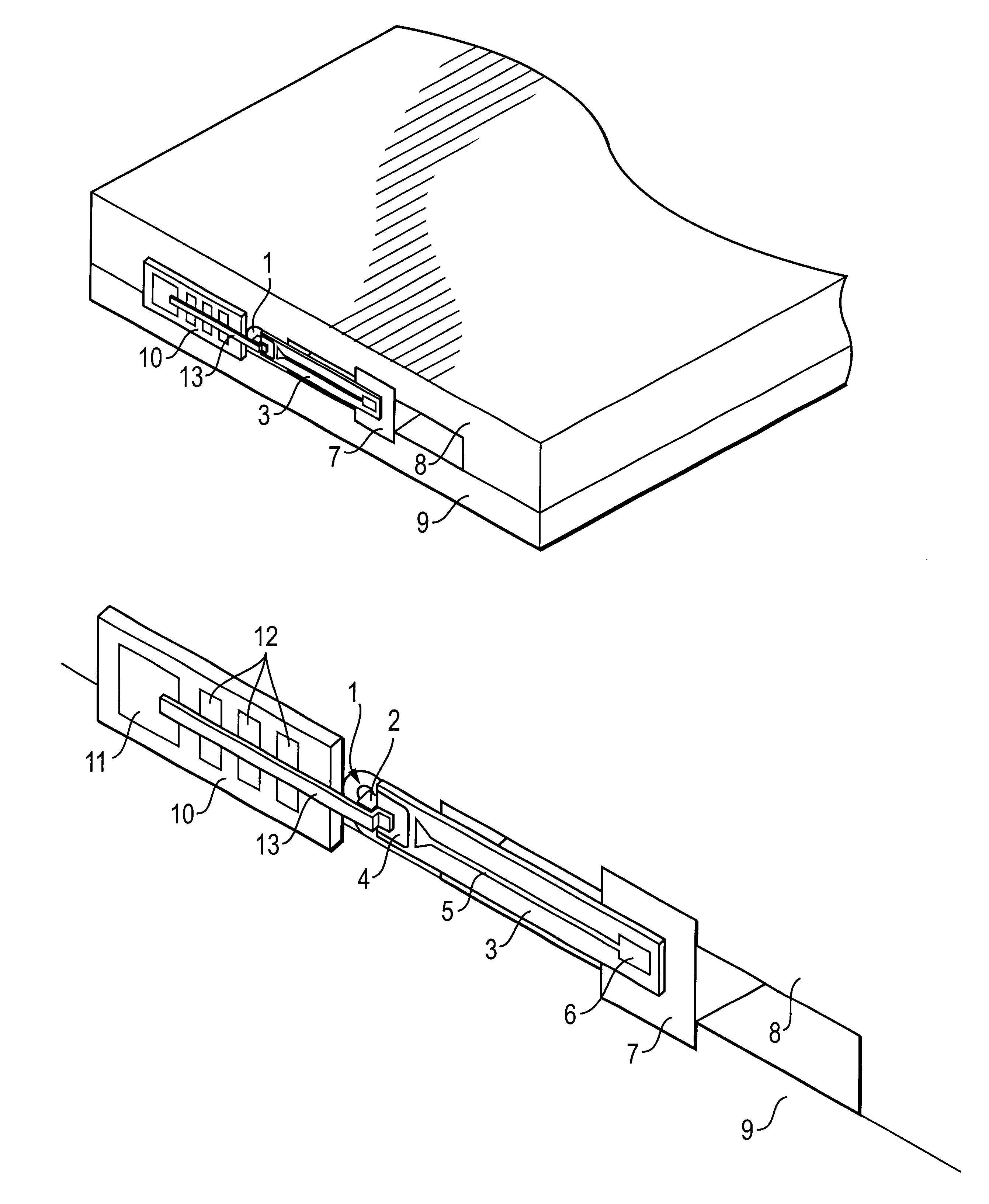
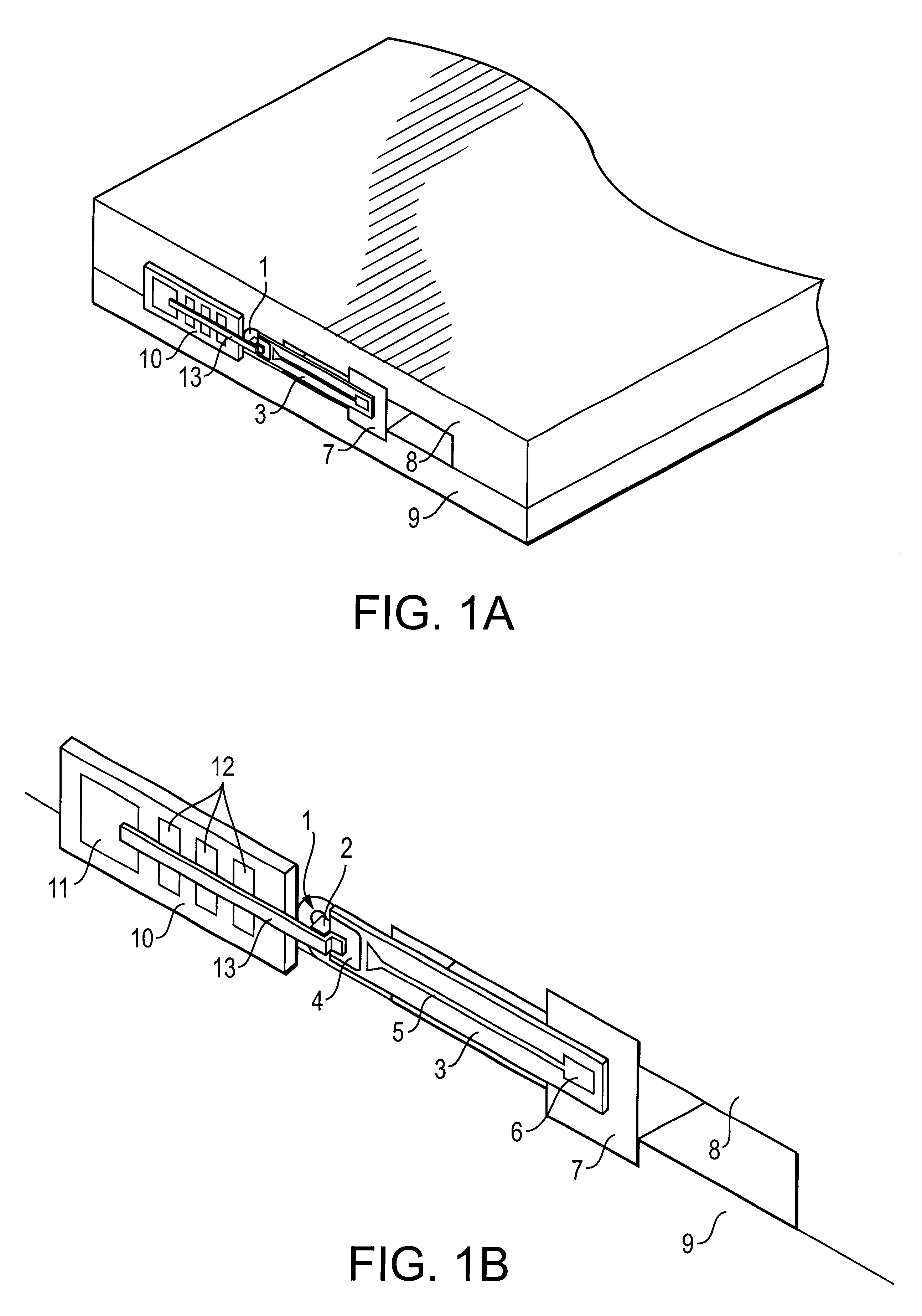
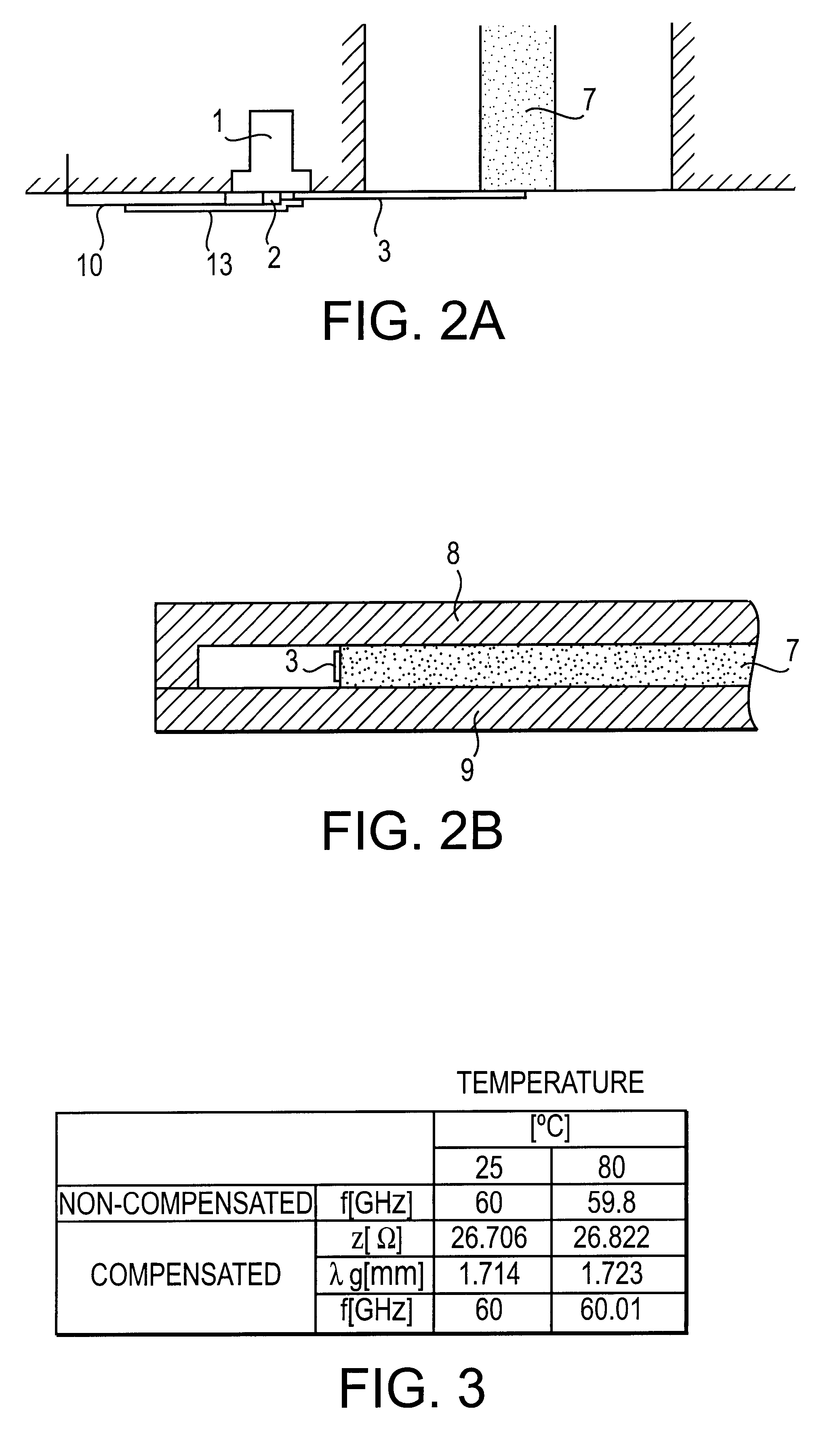
The structure of an oscillator according to a first embodiment of the present invention will be illustrated by referring to FIGS. 1A, 1B, 2A, 2B, and 3.

In FIG. 1A, the main part of the oscillator comprises an oscillating element 1 and a strip line 5 for propagating an output signal from the oscillating element 1. The strip line 5 is disposed on a dielectric plate 3.

A Gunn diode is used as the oscillating element 1. A Gunn-diode chip, which is the typical type of Gunn diode, is enclosed by a pill-shaped package and is electrically connected to an output terminal 2, which is exposed outside the package. Although the placement of the package can arbitrarily be selected, the package in this embodiment is embedded in a metal conductor 8 in such a manner that only the output terminal 2 can be accessed from the outside.

The output terminal 2 is connected to a lead plate 13 for supplying a bias voltage to the Gunn diode 1. The other end of the lead plate 13 is connected to a bias terminal 11...


PUM


Abstract

An oscillator, a dielectric waveguide device and a transmitter incorporating the same, wherein a special temperature-compensating circuit provides a temperature-compensated device with reduced size and cost, and greater productivity. In the oscillator, a dielectric plate having a strip line of a specified length is arranged between conductive plates which enclose a Gunn diode. The oscillation output signal of the Gunn diode is extracted via the strip line. In addition, the sign of the dielectric-constant temperature coefficient of the dielectric plate is set such that changes in the oscillation frequency caused by changes in temperature of the Gunn diode are suppressed.

Description

1. Field of the InventionThe present invention relates to an oscillator, a dielectric waveguide device and a transmitter incorporating the same. More particularly, the invention relates to an oscillator for use at a high-frequency such as a millimeter wave or a micro-wave, in which the temperature dependence of an oscillation frequency is small, and a dielectric waveguide device and a transmitter incorporating the same.2. Description of the Related ArtA millimeter-wave oscillator is an example of a high-frequency oscillator. The millimeter-wave oscillator is used, for example, in a vehicle-collision-avoidance radar system. In a typical type of millimeter-wave oscillator, a solid-state oscillating element such as a Gunn diode is often used.In this case, an oscillation signal outputted from a Gunn diode is guided to a dielectric resonator via a dielectric waveguide, which electromagnetically couples to the dielectric resonator. In this arrangement, the dielectric resonator acts as a p...

Claims


Application Information

Patent Timeline
IPC IPC(8): H03L1/02H03L1/00H03B5/00H03B5/04H03B5/18G01S7/03H03B9/14H01P3/16
CPCH03B5/04H03L1/021H03B5/1847
Inventor HARUTA, KAZUMASAYAMASHITA, SADAO
Owner MURATA MFG CO LTD
Why Eureka
Try Eureka